
This is part 10 in are tang nano series which is a sort of milestone, so we wanted to do something a bit different for this article. In this article we will be going full-circle back to the LED counter example where it all started, but this time we will be implementing the project using software.
To accomplish this there are a few things we need to implement, like an instruction set architecture, a cpu core that can process this bytecode and an assembler to convert our assembly programs into bytecode in our instruction set format.
But like usual before we get into building things, let us take a brief detour to go over some of the theory.
What is a CPU ?
CPUs can mean a lot of different things to different people, so let me start off by explaining what I am talking about. I am referring to a core (we will build in verilog) that will receive code line by line and execute each instruction accordingly.
What this gives you is a general purpose hardware design, where instead of building a specific project, you are building the building-blocks and allowing for external software to "orchestrate" the different internal operations to compose them into many different use-cases.
This is the same way all our devices, like computers, phones, etc. work, you have a processor which implements a specific instruction set architecture, things like the RISC V architecture have been rising in popularity being completely open and free or the x86 architecture has been the default for computer processors.
These processors have a very specific bit-sequence for each instruction and the processor knows how to decode this bit-sequence to understand what to do for each instruction.
Writing code in binary is not that convenient, so typically you have something called an assembler which converts each command from a text representation into the binary representation.
For example we may have an instruction to clear a register called "A", the processor may want to receive this instruction as 01100001, this is the bytecode for this command. Instead the programmer writing this they would write the assembly languages textual representation, something like "CLR A" which the assembler would take and convert into the bytecode version.
There are even higher level abstractions that we won't get into in this article, but typically people don't write assembly programs, they use higher level languages like C or Rust which provide an abstraction layer to write more concise code which then gets compiled into assembly and assembled into bytecode.
The ISA
The ISA (or instruction set architecture) basically defines the syntax, bytecode and behaviour of the software language we are building.
To make an instruction set where you can start to make interesting programs requires most if not all of the following:
- A way to work with data (load data / basic arithmetic)
- variables or storage for calculation (usually general purpose registers)
- A way to get user-input
- A way to output something for a user
- Some kind of conditional statement (for implementing if / else type statements)
- A way to jump from one place to another in code (which allows for loops)
Now "working with data" is a very general sentence which also needs decisions like what kind of data and what operations. You may be making a more complex graphics processor where the instructions perform math operations on matrices like matrix multiplication or you may have special data type operations like linked lists, etc.
For our first processor we will be creating a simple 8-bit processor, this means our registers will be 8-bit are math operations will be 8-bit and our instructions will revolve around 8-bit parameters.
In our processor we will have 4 general purpose registers, as a sort of convention the main register is called AC or accumulator since you generally store the result of operations in this register. The other registers simply will get a letter as there name so we will have A, B and C.
Next for operations we will implement:
- Clear a register
- Invert a register
- Add number to a register
- Add 2 registers together
This will allow us to perform addition and multiplication (since multiplication can be implemented as repeated addition) and using the invert command we can implement subtraction using 2's complement and with subtraction you could theoretically maybe also implement division as a repeated subtraction.
So by implementing these 4 options we get basic arithmetic operations. It is worth mentioning that if multiplication and division were important to you, then I would add a dedicated instruction to perform them in hardware in a single operation as opposed to having to "implement" it in code which is a lot less performant, but for our example I will mostly be using addition.
Besides these 4 commands we will also implement some other things:
- Store AC into one of the other registers
- Output character to user via Screen
- Set LED values
- Way to check if button is pressed as user input
- A way to conditionally jump between lines of code
- A command to wait x milliseconds
- A way to stop the execution of code.
This will give us a good base set of commands to create some programs. The way I decided to implement these commands are as eight instructions where each instruction can have 1 of 4 parameters types.
; CLR A/B/BTN/AC
CLR A    ; clear a register
CLR B    ; clear b register
CLR BTN  ; clear ac if button is pressed
CLR AC   ; clear ac register

; STA A/B/C/LED
STA A    ; store ac in a register
STA B    ; store ac in b register
STA C    ; store ac in c register
STA LED  ; set leds to bottom 6 bits of ac

; INV A/B/C/AC
INV A    ; invert bits of register a
INV B    ; invert bits of register b
INV C    ; invert bits of register c
INV AC   ; invert bits of register ac

; HLT
HLT      ; halt execution (stop program)

; ADD A/B/C/Constant
ADD A    ; ac = ac + a
ADD B    ; ac = ac + b
ADD C    ; ac = ac + c
ADD 20   ; ac = ac + 20

; PRNT A/B/C/Constant (ac should have the screen char index)
PRNT A   ; screen[ac] = a (a should be ascii value)
PRNT B   ; screen[ac] = b (b should be ascii value)
PRNT C   ; screen[ac] = c (c should be ascii value)
PRNT 110 ; screen[ac] = 110

; JMPZ A/B/C/Constant
JMPZ A   ; go to line a in code if ac == 0
JMPZ B   ; go to line b in code if ac == 0
JMPZ C   ; go to line c in code if ac == 0
JMPZ 20  ; go to line 20 in code if ac == 0

; WAIT A/B/C/Constant
WAIT A   ; wait a milliseconds
WAIT B   ; wait b milliseconds
WAIT C   ; wait c milliseconds
WAIT 100 ; wait 100 milliseconds
So as you can see here we have 8 instructions where most of them have 4 variations.
Next we need to decide how we will store this in memory, with 8 operations we need at least 3 bits to differentiate between them, and then for each of them we have 4 options. Since we probably won't be using less then a byte per instruction I propose for this project the following layout:
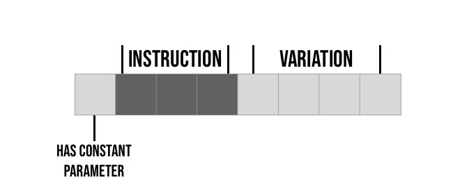
So for example if the first command is CLR then it's four variations would be:
CLR A   ; 00001000 -> 0 000 1000
CLR B   ; 00000100 -> 0 000 0100
CLR BTN ; 00000010 -> 0 000 0010
CLR AC  ; 00000001 -> 0 000 0001
Next let's take a look at the next instruction ADD here we have a constant parameter so it would be represented as follows:
ADD A   ; 00011000 -> 0 001 1000
ADD B   ; 00010100 -> 0 001 0100
ADD C   ; 00010010 -> 0 001 0010
ADD 20  ; 10010001 -> 1 001 0001
The first 3 are exactly like the CLR command, the last option since it is using a constant parameter we also set the 1st bit high.
Since each of the 4 variations have there own bit and only 1-bit is ever on, and also since the commands with constant parameters have there own bit, we can very easily decode these options by simply checking a single bit.
It is worth noting that we didn't actually store the constant value, in the example above we just stored a byte represented the instruction "add constant" but we will need to store another byte in memory with the actual value. This is why we distinguish these commands with the extra flag bit so we will know when we need to load another byte with the value and when not.
Now don't worry if some of this feels random, if this is your first CPU design the decisions I took above of which instructions to implement and how to represent them may seem arbitrary, and the truth is they are basically arbitrary.
You have full control over what and how to implement the architecture, and by building and using your architecture it will give you ideas on improvements or changes that you can make in future designs. So these are arbitrary decisions based on previous instruction sets I have worked with, in an attempt to go for the simplest / minimal instruction set, that would still be usable and would provide an example of the concepts and a starting point for your future explorations in ISA.
Besides experimenting, another good way to learn more is by exploring other ISAs. Our instruction set only has about 8 instructions but x86 on the other hand has (depending on how you count) closer to 1000, so there are alot of other things that can be added. Try to look at instruction sets that perform things similar to what you are trying to do.
For example you can look at old processor instruction sets like the 8085, or you may want to look at the avr instruction set used by arduinos as examples of mcu type instruction sets. Like mentioned above there is the risc series of instruction sets and the x86 instruction set which is what your computer is probably using.
There are even "educational" instruction sets developed for learning purposes, without real processors that use them like Mano machine instruction set or MMIX.
With the instruction set planned out, let us go over some implementation theory.
CPU Core
Implementing a core that can process an instruction set is usually done with a pipeline design. Not to be confused by pipelining which is parallelising the execution pipeline, I am more referring to the steps themselves required to execute a single command.
In our processor we will have the following pipeline stages:
- Fetch - load the next command from memory
- Decode - process the command / prepare parameters if possible
- Retrieve - optionally fetch another byte if constant parameter is used
- Execute - Run the command once everything is loaded
This is typically the stages in most processors of this type, although sometimes there are more stages for things like writing data back to memory we don't have in our ISA or sometimes these steps may be divided differently.
Modern processors perform all these steps in parallel, so while line 1 is executing, line 2 is retrieving, and line 3 is decoding and line 4 is fetching. Doing this can dramatically speed up your processor as you are always "executing".
We won't be doing this as it raises more complexities, for example, let's say we jump to another line of code, then the lines currently being fetched / decoded are no longer relevant and we would need to handle that, also the retrieve step is optional so we would need to account for that. To keep things simple, we will only be performing one of these steps at a time.
Let's go over how we will implement these stages:
The Fetch Stage
We will have a register which stores where we are in our program, this is usually called PC or "program counter" as it is a counter that stores the line number.
In the fetch stage we will request the byte in memory at the address pointed to by the PC register, this byte that we will receive is the command byte in our bytecode format.
The Decode Stage
Here we will take the byte we read and do a little processing on it. We will check whether or not we need to go to the retrieve stage, this is based on whether or not the bit for the "has constant parameter" is high.
In the event the parameter is not in the next byte then we can also prepare the parameter already based on the variation.
The Retrieve Stage
If the parameter was a constant, requiring us to read another byte from memory with its value, then in this stage we will request the next byte from memory and store the value as the parameter for the current instruction.
The Execute Stage
This is the where we have everything we need, and here we actually perform the desired operation. For each instruction is is a bit different, but for example if we are currently executing the instruction ADD B then here we would do: ac <= ac + b.
By implementing these four stages we will have a processor capable of running our instruction set. With the theory done, let's get into some implementation:
Some Prerequisites
Before we start implementing our cpu verilog module we will need the screen.v and text.v modules which we have been using along with the font file. (everything can be found in our github page here along with links to the articles where these screen modules were implemented).
Besides these we will also need a module to read our code. We will be storing our code in the external flash, as it is easy to program, but that means we need a way to load a specific byte from flash. For this we can repurpose our flash module which we created originally created here.
The main change we need to make there, is it used to read a whole "page" of bytes and we only want it to read a single byte.
I won't go through it again, as it is the same as the article linked above, but here is the module after the changes:
`default_nettype none

module flash
#(
  parameter STARTUP_WAIT = 32'd10000000
)
(
    input clk,
    output reg flashClk = 0,
    input flashMiso,
    output reg flashMosi = 0,
    output reg flashCs = 1,
    input [10:0] addr,
    output reg [7:0] byteRead = 0,
    input enable,
    output reg dataReady = 0
);

  reg [7:0] command = 8'h03;
  reg [7:0] currentByteOut = 0;

  localparam STATE_INIT_POWER = 8'd0;
  localparam STATE_LOAD_CMD_TO_SEND = 8'd1;
  localparam STATE_SEND = 8'd2;
  localparam STATE_LOAD_ADDRESS_TO_SEND = 8'd3;
  localparam STATE_READ_DATA = 8'd4;
  localparam STATE_DONE = 8'd5;

  reg [23:0] dataToSend = 0;
  reg [8:0] bitsToSend = 0;

  reg [32:0] counter = 0;
  reg [2:0] state = 0;
  reg [2:0] returnState = 0;

  always @(posedge clk) begin
    case (state)
      STATE_INIT_POWER: begin
        if (counter < STARTUP_WAIT)
          counter <= counter + 1;
        else if (enable) begin
          state <= STATE_LOAD_CMD_TO_SEND;
          counter <= 32'b0;
          dataReady <= 0;
          currentByteOut <= 0;
        end
      end
      STATE_LOAD_CMD_TO_SEND: begin
          flashCs <= 0;
          dataToSend[23-:8] <= command;
          bitsToSend <= 8;
          state <= STATE_SEND;
          returnState <= STATE_LOAD_ADDRESS_TO_SEND;
      end
      STATE_SEND: begin
        if (counter == 32'd0) begin
          flashClk <= 0;
          flashMosi <= dataToSend[23];
          dataToSend <= {dataToSend[22:0],1'b0};
          bitsToSend <= bitsToSend - 1;
          counter <= 1;
        end
        else begin
          counter <= 32'd0;
          flashClk <= 1;
          if (bitsToSend == 0)
            state <= returnState;
        end
      end
      STATE_LOAD_ADDRESS_TO_SEND: begin
        dataToSend <= {13'b0,addr};
        bitsToSend <= 24;
        state <= STATE_SEND;
        returnState <= STATE_READ_DATA;
      end
      STATE_READ_DATA: begin
        if (counter[0] == 1'd0) begin
          flashClk <= 0;
          counter <= counter + 1;
          if (counter[3:0] == 0 && counter > 0) begin
            byteRead <= currentByteOut;
            state <= STATE_DONE;
          end
        end
        else begin
          flashClk <= 1;
          currentByteOut <= {currentByteOut[6:0], flashMiso};
          counter <= counter + 1;
        end
      end
      STATE_DONE: begin
        dataReady <= 1;
        flashCs <= 1;
        counter <= STARTUP_WAIT;
        if (~enable) begin
          state <= STATE_INIT_POWER;
        end
      end
    endcase
  end
endmodule
Again if something here is unclear, we go through it in this article.
With that setup out of the way we can now get into building our cpu module.
The Implementation
To begin let's create a file called cpu.v with the following module definition:
module cpu(
    input clk,

    output reg [10:0] flashReadAddr = 0,
    input [7:0] flashByteRead,
    output reg enableFlash = 0,
    input flashDataReady,

    output reg [5:0] leds = 6'b111111,

    output reg [7:0] cpuChar = 0,
    output reg [5:0] cpuCharIndex = 0,
    output reg writeScreen = 0,

    input reset,
    input btn
);

endmodule
The first input is our clock signal, next we have the 4 ports required to control the flash module. To interface with the flash module we need to set the address we want to read in flashReadAddr, then set enableFlash high to start the read process. We then need to wait for flashDataReady to go high signifying that the byte was read, where we can then take the value from flashByteRead.
Next we have an output register to control the on-board LEDs, we initialise this register to all ones, since our LEDs are active low, so this will turn them all off by default.
Next we have 3 ports for writing characters to the screen. The way this will work is we will put an ascii character into cpuChar and we will put the character index on screen into cpuCharIndex. We will then set writeScreen high to trigger the value to be stored in screen memory to be displayed.
We will have a 64-byte register where we will store 64 character values, and these values will be mapped to each of the screen character indices. So for example if we set character 0 to 'A' that means the first character (top left) should be an 'A' and so on.
Finally we have two ports for buttons, the reset button will restart the processor, rerunning the code from line zero, and the second button called btn is a general purpose button used with the CLR BTN command to be included in assembly programs.
Next we can add some localparam definitions:
localparam CMD_CLR = 0;
localparam CMD_ADD = 1;
localparam CMD_STA = 2;
localparam CND_INV = 3;
localparam CMD_PRNT = 4;
localparam CMD_JMPZ = 5;
localparam CMD_WAIT = 6;
localparam CMD_HLT = 7;
This defines the command number for each of our 8 commands. Like we spoke about in the ISA section, we will have 3 bits which will determine which of the 8 instructions is chosen. Those 3 bits will represent one of these 8 localparam definitions.
Next we will need some registers:
reg [5:0] state = 0;
reg [10:0] pc = 0;
reg [7:0] a = 0, b = 0, c = 0, ac = 0;
reg [7:0] param = 0, command = 0;

reg [15:0] waitCounter = 0;
First off we have a register, for the CPUs state machine, this is the state machine which implements the execution pipeline we talked about. Next we have a register for the program counter which stores which line we are currently on in the code / memory, we start from address 0 of the flash memory.
Next we have the four main registers used in our ISA: A, B, C and AC each of which are 8-bits long.
After this we have another two registers, one which stores the current command and one which stores the current parameter. So for example if our command is ADD C then this would be stored in the command register and the value of the c register would be stored in param, and if the current instruction has a constant parameter then the constant parameter will be stored in param instead.
Finally we have a register for the WAIT command. This command needs to wait x milliseconds, at 27Mhz, each millisecond is 27,000 clock cycles, so we have a 16-bit register to count 27,000 clock cycles to know we have waited 1 millisecond.
Next let's define the states in our cpu's state machine:
localparam STATE_FETCH = 0;
localparam STATE_FETCH_WAIT_START = 1;
localparam STATE_FETCH_WAIT_DONE = 2;
localparam STATE_DECODE = 3;
localparam STATE_RETRIEVE = 4;
localparam STATE_RETRIEVE_WAIT_START = 5;
localparam STATE_RETRIEVE_WAIT_DONE = 6;
localparam STATE_EXECUTE = 7;
localparam STATE_HALT = 8;
localparam STATE_WAIT = 9;
localparam STATE_PRINT = 10;
We have states for our 4 pipeline stages: fetch, decode, retrieve and execute. Commands that interface with the flash memory like fetch and retrieve have 3 states, one to initialize the read operation, one to wait for the flash read operation to start and one to save the result once the operation is complete.
The reason this is done in 3 steps instead of just 1 or 2 for example is to sort of debounce the flags. If we immediately check if the dataReady flag is high, we may accidentally read the previous read operation's dataReady flag and think our data is ready. By first waiting for the data ready flag to go low, and only then to check if it goes high we ensure that is it high from our current operation.
Besides for these states we have a special state for HALT which basically just stops the CPU from running once the HLT instruction was executed. Finally we have special states for waiting x milliseconds as-well as printing to the screen as these operations take more then a single clock cycle.
Implementing the State Machine
To begin with, our main always block should take care of the reset condition. If the reset button is pressed it should override everything else and reset all variables to their initial values:
always @(posedge clk) begin
    if (reset) begin
        pc <= 0;
        a <= 0;
        b <= 0;
        c <= 0;
        ac <= 0;
        command <= 0;
        param <= 0;
        state <= STATE_FETCH;
        enableFlash <= 0;
        leds <= 6'b111111;
    end
    else begin
        case(state)
            // states here
        endcase
    end
end
We make reset take precedence over our state machine by putting the entire state machine in the else section.
Our first state is the "Fetch" operation where we need to load the byte in memory at the address stored in our program counter register:
STATE_FETCH: begin
    if (~enableFlash) begin
        flashReadAddr <= pc;
        enableFlash <= 1;
        state <= STATE_FETCH_WAIT_START;
    end
end
STATE_FETCH_WAIT_START: begin
    if (~flashDataReady) begin
        state <= STATE_FETCH_WAIT_DONE;
    end
end
STATE_FETCH_WAIT_DONE: begin
    if (flashDataReady) begin
        command <= flashByteRead;
        enableFlash <= 0;
        state <= STATE_DECODE;
    end
end
These three states interface with the flash module in-order to read the byte. The first state sets the enableFlash pin high, it sets the desired address to the program counter and then we move onto the state where we wait for the read operation to start.
In the STATE_FETCH_WAIT_START state we simply wait for the ready flag to go low, again this is to make sure we don't accidently read the flag's status from the previous operation by mistake.
The final stage STATE_FETCH_WAIT_DONE waits for the data ready flag to go back high, where we can then store the byte read in command and we disable the flash until we need it again so that it can go back to its idle state.
STATE_DECODE: begin
    pc <= pc + 1;
    // command has constant param
    if (command[7]) begin
        state <= STATE_RETRIEVE;
    end else begin
        param <= command[3] ? a : command[2] ? b : command[1] ? c : ac;
        state <= STATE_EXECUTE;
    end
end
The next pipeline stage is the decode stage where we first off increment the program counter since we just read the current byte. We then check whether the current command has a constant parameter (which requires reading an extra byte from the flash memory) or whether the parameter is one of our 4 main registers.
If you remember from our ISA, we set the 8th-bit (bit index 7) high if the current instruction requires loading a constant parameter so it is easy to check in this case we will go to the retrieve stage. In the event this command doesn't have a constant parameter we store one of the other registers into param based on which of the 4 bits in the instruction are set.
So ADD A will have bit index 3 set whereas ADD B will have bit index 2 set. Not all commands have parameters, like HLT, or some commands have other parameters like STA LED where the parameter is the led register. But it doesn't hurt to store one of the 4 registers into param so it is easier to just do it always instead of only doing it when required.
The next 3 states are for the retrieve stage. These are almost identical to the fetch instructions except for what they do when the byte has been read:
STATE_RETRIEVE: begin
    if (~enableFlash) begin
        flashReadAddr <= pc;
        enableFlash <= 1;
        state <= STATE_RETRIEVE_WAIT_START;
    end
end
STATE_RETRIEVE_WAIT_START: begin
    if (~flashDataReady) begin
        state <= STATE_RETRIEVE_WAIT_DONE;
    end
end
STATE_RETRIEVE_WAIT_DONE: begin
    if (flashDataReady) begin
        param <= flashByteRead;
        enableFlash <= 0;
        state <= STATE_EXECUTE;
        pc <= pc + 1;
    end
end
First two states are exactly the same as in the fetch stage, we could have combined them if we had another register to store where to go next, but I decided to duplicate them as I feel it is a little simpler to understand.
In the STATE_RETRIEVE_WAIT_DONE state we store the byte read into param and go to the execute stage. We also increment the program counter again, since we read another byte and have to advance to the next byte address to receive the next instruction for next time.
The next state is where most of the heavy lifting goes, in the execute stage we actually perform the desired instruction so let's start with the outline and then we will add each command in:
STATE_EXECUTE: begin
    state <= STATE_FETCH;
    case (command[6:4])

    endcase
end
In this state we have another case statement where we check the 3 bits which define which instruction we have currently loaded. In this case statement we use our 8 command localparam definitions we defined above.
The first command we will implement is CLR:
CMD_CLR: begin
    if (command[0])
        ac <= 0;
    else if (command[1])
        ac <= btn ? 0 : (ac ? 1 : 0);
    else if (command[2])
        b <= 0;
    else if (command[3])
        a <= 0;
end
Here we are clearing registers so the param doesn't really help us, we go over the 4 bits which choose which variation we are working on and perform the corresponding action. Most of the variations simply set a register to zero, except for CLR BTN which only clears ac if the user button is currently pressed otherwise it keeps the current value of ac.
The next command we will implement is ADD this command is a lot simpler as the value is always stored in ac and the parameter is already stored in param even in the event of a constant parameter thanks to the retrieve stage.
CMD_ADD: begin
    ac <= ac + param;
end
Next we have STA which stores the ac register into a destination register based on the variation:
CMD_STA: begin
    if (command[0])
        leds <= ~ac[5:0];
    else if (command[1])
        c <= ac;
    else if (command[2])
        b <= ac;
    else if (command[3])
        a <= ac;
end
Most of the 4 variations are simply storing the ac register into a different register, again since the value in each of the operations is ac it wouldn't really help us storing it in param so we need to handle each of the 4 variations here. The first variation inverts the value and only takes the bottom 6 bits since again the LEDs are active low and we only have 6 of them.
The next instruction is the INV instruction, which simply inverts the bits of one of the registers:
CND_INV: begin
    if (command[0])
        ac <= ~ac;
    else if (command[1])
        c <= ~c;
    else if (command[2])
        b <= ~b;
    else if (command[3])
        a <= ~a;
end
Nothing special to explain here, each variation is handled like before, and each simply flips a register's bits.
The next command is the PRNT instruction, which updates the character memory which is mapped to the screen.
CMD_PRNT: begin
    cpuCharIndex <= ac[5:0];
    cpuChar <= param;
    writeScreen <= 1;
    state <= STATE_PRINT;
end
We set the screen character index to the bottom 6 bits of ac (only the bottom 6 since there is only 64 positions) and the actual ascii character value is stored in param. We then set writeScreen to 1 in-order to trigger the screen memory update and we go to the STATE_PRINT state to get an extra clock cycle for this instruction to give the screen memory time to write the changes.
The next command is JMPZ which jumps to a different line in code if the ac register currently equals 0.
CMD_JMPZ: begin
    pc <= (ac == 8'd0) ? {3'b0,param} : pc;
end
The address where we want to jump to is already stored in param so here we simply check if ac equals zero, in which case we set the current value of pc to the address we want to go to. Otherwise we keep the current value of pc effectively doing nothing.
It is worth noting, our program counter is 11-bits long and our parameters are only 8-bits long, meaning that even though are programs can theoretically be 2048 lines long (as our program counter will go up to this value before rolling back to zero), our jump instruction can only jump to an address up to line 256. This is a limitation of our ISA which we will have to work around when designing our programs.
The next instruction we need to implement is the WAIT instruction where we wait x milliseconds, where x is the value stored in param
CMD_WAIT: begin
    waitCounter <= 0;
    state <= STATE_WAIT;
end
Here we don't really do anything we just jump to the STATE_WAIT state where we will do the waiting before running the next command.
The final instruction is the HLT instruction which simply stops execution:
CMD_HLT: begin
    state <= STATE_HALT;
end
Here also we just jump to a special state where we will just do nothing as we have finished the program.
This finished the internal case statement and implements all the instructions in our ISA. We can now return to implementing the final states in our outer case statement which are these special states we added for certain instructions.
The first was the STATE_PRINT state where we just wanted an extra clock cycle to give time for the screen memory to update. So in this state we don't do anything we just go back to our standard pipeline:
STATE_PRINT: begin
    writeScreen <= 0;
    state <= STATE_FETCH;
end
Next we have the state for waiting x milliseconds:
STATE_WAIT: begin
    if (waitCounter == 27000) begin
        param <= param - 1;
        waitCounter <= 0;
        if (param == 0)
            state <= STATE_FETCH;
    end else
        waitCounter <= waitCounter + 1;
end
We count up 27,000 clock cycles which equals 1 milliseconds and then decrement param. So if param was 20 we will do this 20 times, essentially waiting 20 milliseconds and then when param is 0 we go back to our regular pipeline.
Finally we have the STATE_HALT state where we don't actually want to do anything, we could have left this off even but I like to include it to stress that we are doing nothing here.
STATE_HALT: begin
end
With that our cpu module is complete and should now be able to run programs written with out instruction set.
The Top Module
The next thing we need to implement is the top module which will wire up all our other modules, to start off with create a file called top.v with the following module definition:
`default_nettype none

module top
#(
  parameter STARTUP_WAIT = 32'd10000000
)
(
    input clk,
    output ioSclk,
    output ioSdin,
    output ioCs,
    output ioDc,
    output ioReset,
    output flashClk,
    input flashMiso,
    output flashMosi,
    output flashCs,
    input btn1,
    input btn2,
    output [5:0] led
);

endmodule
For ports, we have the clock signal, the 5 ports for the screen, we have another 4 ports for the external flash, two ports for the two on-board buttons and our 6 LEDs.
Next let's create some intermediate registers for our buttons:
reg btn1Reg = 1, btn2Reg = 1;
always @(negedge clk) begin
    btn1Reg <= btn1 ? 0 : 1;
    btn2Reg <= btn2 ? 0 : 1;
end
This serves two purposes, 1 it inverts the button, the buttons are also active low, but I prefer using active high so we flip them (purely personal preference). The other thing we are doing is we are separating the button input from the button value. Muxing in a new 1 or 0 based on the input pin, this is useful here since the buttons are on the 1.8v bank and our other components are on the 3.3v banks so this allows the router to separate the value from the bank so we don't get a conflict.
Next we have the screen and text engine, here the setup is like in all our articles:
wire [9:0] pixelAddress;
wire [7:0] textPixelData;
wire [5:0] charAddress;
reg [7:0] charOutput = "A";

screen #(STARTUP_WAIT) scr(
    clk,
    ioSclk,
    ioSdin,
    ioCs,
    ioDc,
    ioReset,
    pixelAddress,
    textPixelData
);

textEngine te(
    clk,
    pixelAddress,
    textPixelData,
    charAddress,
    charOutput
);
After these we can instantiate our flash module:
wire [10:0] flashReadAddr;
wire [7:0] byteRead;
wire enableFlash;
wire flashDataReady;

flash externalFlash(
    clk,
    flashClk,
    flashMiso,
    flashMosi,
    flashCs,
    flashReadAddr,
    byteRead,
    enableFlash,
    flashDataReady
);
Leaving the last module we need to instantiate be our cpu module:
wire [7:0] cpuChar;
wire [5:0] cpuCharIndex;
wire writeScreen;

cpu c(
    clk,
    flashReadAddr,
    byteRead,
    enableFlash,
    flashDataReady,
    led,
    cpuChar,
    cpuCharIndex,
    writeScreen,
    btn1Reg,
    btn2Reg
);
With that we have all our modules instantiated and hooked up to each other. The last thing we need to do is our screen memory and to map it to the text engine so it will be displayed on screen.
We already created the wires here for the character, character index and the flag wire writeScreen which tells us when to store a new character.
To implement this screen memory we can add the following:
reg [511:0] screenBuffer = 0;
always @(posedge clk) begin
    if (writeScreen)
        screenBuffer[{cpuCharIndex, 3'b0}+:8] <= cpuChar;
    else
        charOutput <= screenBuffer[{charAddress, 3'b0}+:8];
end
We start off by creating the screen buffer register, which needs to be big enough to hold 64 different characters. We then have an always block where if the writeScreen flag is set we store the value from cpuChar into the screen buffer at character index cpuCharIndex. We multiply by 8 (by shifting 3 lower bits in) since each character is 8 bits long.
When the writeScreen flag is not high, we instead interface with the text engine module and set the desired character to display from memory based on the charAddress which stores the character index of the current character being drawn.
Constraints File
Next we can create our constraints file, we have quite a lot of constraints relative to our other projects, since we are using both the screen, leds, buttons and flash.
If you are manually compiling your project your constraints file will need to look like the following:
IO_LOC  "clk" 52;
IO_PORT "clk" PULL_MODE=UP;

IO_LOC  "ioCs" 36;
IO_PORT "ioCs" DRIVE=8 IO_TYPE=LVCMOS33 PULL_MODE=UP;
IO_LOC  "ioDc" 39;
IO_PORT "ioDc" DRIVE=8 IO_TYPE=LVCMOS33 PULL_MODE=UP;
IO_LOC  "ioReset" 25;
IO_PORT "ioReset" DRIVE=8 IO_TYPE=LVCMOS33 PULL_MODE=UP;
IO_LOC  "ioSdin" 26;
IO_PORT "ioSdin" DRIVE=8 IO_TYPE=LVCMOS33 PULL_MODE=UP;
IO_LOC  "ioSclk" 27;
IO_PORT "ioSclk" DRIVE=8 IO_TYPE=LVCMOS33 PULL_MODE=UP;

IO_LOC  "flashClk" 59;
IO_PORT "flashClk" IO_TYPE=LVCMOS33;
IO_LOC  "flashMiso" 62;
IO_PORT "flashMiso" IO_TYPE=LVCMOS33;
IO_LOC  "flashMosi" 61;
IO_PORT "flashMosi" IO_TYPE=LVCMOS33;
IO_LOC  "flashCs" 60;
IO_PORT "flashCs" IO_TYPE=LVCMOS33;

IO_LOC  "btn1" 3;
IO_PORT "btn1" IO_TYPE=LVCMOS18;
IO_LOC  "btn2" 4;
IO_PORT "btn2" IO_TYPE=LVCMOS18;

IO_LOC  "led[0]" 10;
IO_PORT "led[0]" DRIVE=8 IO_TYPE=LVCMOS18;
IO_LOC  "led[1]" 11;
IO_PORT "led[1]" DRIVE=8 IO_TYPE=LVCMOS18;
IO_LOC  "led[2]" 13;
IO_PORT "led[2]" DRIVE=8 IO_TYPE=LVCMOS18;
IO_LOC  "led[3]" 14;
IO_PORT "led[3]" DRIVE=8 IO_TYPE=LVCMOS18;
IO_LOC  "led[4]" 15;
IO_PORT "led[4]" DRIVE=8 IO_TYPE=LVCMOS18;
IO_LOC  "led[5]" 16;
IO_PORT "led[5]" DRIVE=8 IO_TYPE=LVCMOS18;
If you are using the Lushay Code extension, then you can import the flash, leds and buttons from the "Add from template" button and then only add the screen port constraints manually.
You should have something like the following:
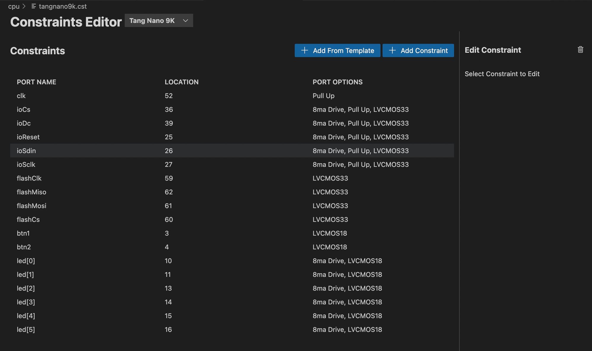
We could technically now build and run our project, but without a software program written in our ISA it won't do much. So before building and running our cpu core let's write a program using our new ISA.
Testing Our ISA
To get started let's create a new folder for our programs, we can simply call this programs and then inside let's create our first software script. Like mentioned above as a first example, let's recreate the counter example project we created in episode one, this time using our ISA. To do this let's create a file in our programs folder called counter.prog (name & extension doesn't really matter)
CLR AC
STA B           ; B holds the current counter
JMPZ 10

.org 10
ADD B           ; reload current counter
ADD 1           ; inc AC by 1
STA B           ; store counter in B
STA LED
WAIT 250
WAIT 250
WAIT 250
WAIT 250        ; wait 1 second
CLR AC          ; clear AC so we jump in the next line
JMPZ 10
In this program we start off by storing 0 in register B which we will use to store the current count. We then create a new section at address 10 using the .org preprocessor. This is a useful feature, since we are performing "jump to address" instructions it is helpful to have a way to say this code is located at address x.
The rest of the code is our main loop, here we start by adding the current counter value from the b register along with 1 to increment it. We then store the value back into b and also store the value in the LEDs to display the current value. After this we wait 1 second (split into 4 instructions since the max parameter value is 255). Finally we clear ac so that we can jump back to the beginning of our loop, again incrementing and displaying the counter value each time.
Pretty cool, we have our first program ready, the next step is to create a binary file with the "assembled" version of our program, where each command here is converted into its binary format.
We can do this by creating an assembler program.
The Assembler
An assembler, simply takes in assembly code and performs the mapping for us to binary form. We also have the added .org preprocessor we used to specify where the next lines of code are positioned in memory making jumps easier.
To get started create a file in the scripts folder called assembler.js:
const fs = require('fs');
const path = require('path');

const file = process.argv[2];
if (!file) {
    console.error('No file supplied, usage `node scripts/assembler.js <filename>`');
    process.exit(1);
}
try {
    const fileStat = fs.statSync(file);

    if (fileStat.isDirectory()) {
        console.error(`Supplied file (${file}) is a directory`);
        process.exit(1);
    }
} catch(e) {
    if (e.code === 'ENOENT') {
        console.error(`Could not find file ${file}`);
        process.exit(1);
    }
}
We start off our program getting the assembly file's name from argv. This variable stores all command line arguments from the terminal that were specified when running the script. So for example if we run in the terminal node assembler.js counter.prog then argv[0] would be node argv[1] would be the script itself assembler.js and argv[2] should be the name of our assembly script counter.prog.
The rest of the code here just does some checks, like making sure a file was specified, making sure the file exists, and making sure the file is not a directory, but rather a standard file.
After this we need to load the file in and split it up into seperate lines of code:
const fileContents = fs.readFileSync(file).toString();
const lines = fileContents.split('\n').map((line) => {
    return line.split(';').shift().trim()
).filter((line) => !!line);
The first line reads the file as a string into fileContents. The next line splits the file up into seperate lines and maps each line in-order to clean it up. The map function is called on an array, and you pass it another function, it will then send each value from the array into the function, and the map function will return a new array, where each value is replaced with whatever the function returns.
Here we take each line of code, and return a new string which is the line split by ; which we will use to start a comment, So if we had a line like: ADD A ; add a to ac the the split would turn this into an array of two elements: ['ADD A ', 'add a to ac']. We then call shift on this array to only take the first element, as we don't care about the comment, in our example this would return 'ADD A ' and then we call trim to remove any whitespace characters from each end, basically removing the extra spaces leaving us with 'ADD A'.
After mapping our array elements, we also call filter which will remove any empty lines, leaving us with only full lines of code.
Next we can create a map to store what goes in each memory address:
let pc = 0;
const memoryMap = {}
pc will be a running counter to store where we are in memory, allowing for our .org preprocessor to modify it.
Next we will create an array of regular expressions to match the commands being entered, We could have used simple text matching for most commands, but the commands with constant parameters won't be an exact match so we need to use something like "regular expressions" to dynamically match them.
const commands = [
    { regex: /^CLR A$/i,  byte: 0b00001000 },
    { regex: /^CLR B$/i,  byte: 0b00000100 },
    { regex: /^CLR BTN$/i,  byte: 0b00000010 },
    { regex: /^CLR AC$/i, byte: 0b00000001 },
    { regex: /^ADD A$/i,  byte: 0b00011000 },
    { regex: /^ADD B$/i,  byte: 0b00010100 },
    { regex: /^ADD C$/i,  byte: 0b00010010 },
    { regex: /^ADD ([0-9A-F]+?)([HBD]?)$/i,  byte: 0b10010001, hasConstant: true },
    { regex: /^STA A$/i,   byte: 0b00101000 },
    { regex: /^STA B$/i,   byte: 0b00100100 },
    { regex: /^STA C$/i,   byte: 0b00100010 },
    { regex: /^STA LED$/i, byte: 0b00100001 },
    { regex: /^INV A$/i,  byte: 0b00111000 },
    { regex: /^INV B$/i,  byte: 0b00110100 },
    { regex: /^INV C$/i,  byte: 0b00110010 },
    { regex: /^INV AC$/i, byte: 0b00110001 },
    { regex: /^PRNT A$/i,  byte: 0b01001000 },
    { regex: /^PRNT B$/i,  byte: 0b01000100 },
    { regex: /^PRNT C$/i,  byte: 0b01000010 },
    { regex: /^PRNT ([0-9A-F]+?)([HBD]?)$/i,  byte: 0b11000001, hasConstant: true },
    { regex: /^JMPZ A$/i,  byte: 0b01011000 },
    { regex: /^JMPZ B$/i,  byte: 0b01010100 },
    { regex: /^JMPZ C$/i,  byte: 0b01010010 },
    { regex: /^JMPZ ([0-9A-F]+?)([HBD]?)$/i,  byte: 0b11010001, hasConstant: true },
    { regex: /^WAIT A$/i,  byte: 0b01101000 },
    { regex: /^WAIT B$/i,  byte: 0b01100100 },
    { regex: /^WAIT C$/i,  byte: 0b01100010 },
    { regex: /^WAIT ([0-9A-F]+?)([HBD]?)$/i,  byte: 0b11100001, hasConstant: true },
    { regex: /^HLT$/i,  byte: 0b01110000 },
];
In a regular expression the ^ means start of string and the $ mean the end of a string. Regular expressions also use / instead of ' to wrap the string and the added i flag after each regular expression tell it that it is case insensitive.
So most of the entries here are exact matches, for example if we see INV AC this should be mapped to the byte 0b00110001. But the commands with a constant parameter have two sets of brackets, denoting to capture groups. This means we tell the regular expression engine to capture whatever is between the brackets and store it whenever we perform a match on this regular expression.
Inside instead of having a constant string, we have a range of allowed characters. So for constant parameters we can accepts any number and the letters a-f to also support hex numbers. To different between the different number systems we also have the second capture group where you can optionally end the number off with H for hex, B for binary and D for decimal, this will default to decimal if nothing is specified. For these special cases we also add a flag hasConstant and set it to true so that we will know to add another byte with the constant value.
With all our commands defined, we can now go over each line of code and perform the conversion:
for (const line of lines) {
    const orgMatch = line.match(/\.org ([0-9A-F]+)([HBD])?/i);
    if (orgMatch) {
        const memoryAddressStr = orgMatch[1];
        const type = (orgMatch[2] || 'd').toLowerCase();
        const memoryAddress = parseInt(memoryAddressStr, type == 'd' ? 10 : type == 'h' ? 16 : 2);
        pc = memoryAddress;
        continue;
    }
    for (const command of commands) {
        const commandMatch = line.match(command.regex);
        if (commandMatch) {
            memoryMap[pc] = command.byte;
            pc += 1;
            if (command.hasConstant) {
                const constantStr = commandMatch[1];
                const constantType = (commandMatch[2] || 'd').toLowerCase();
                const constant = parseInt(constantStr, constantType == 'd' ? 10 : constantType == 'h' ? 16 : 2);
                const constantSized = constant % 256;
                if (constant !== constantSized) {
                    console.warn(`Line ${line} has an invalid constant`);
                }
                memoryMap[pc] = constantSized;
                pc += 1;
            }
            break;
        }
    }
}
We start off by checking if the line matches our .org preprocessor. In which case we take the two values captured which are the memory address and the number type (like hex, decimal or binary). We use parseInt with the correct base to convert the address from string into a number and we set pc to this number so that the next command we go over will be at this address.
If the current line wasn't an .org preprocessor directive, we go through all our command matchers until we find one that works. Once we found a match we store the byte version in our memory map at the address pointed to by pc.
The rest of the code just parses the constant parameter similar to how we did it with the .org preprocessor. this constant parameter also gets stored as the next byte in our memory map.
Now after this loop we don't really have a complete array of bytes we can use as our bytecode, instead we have a map between addresses and bytecode, somethings like:
{
    0: 0b01101000,
    1: 0b01000100,
    10: 0b01110000
}
In this example we would need an array of 11 bytes, where only 3 of the bytes are defined and the rest are blank. These gaps are created because of the .org preprocessor.
To convert this to an array of bytes, we first need to know what the largest address is:
const largestAddress = Object.keys(memoryMap)
    .map((key) => +key)
    .sort((a, b) => a > b ? -1 : a < b ? 1 : 0)
    .shift();

if (typeof largestAddress === 'undefined') {
    console.error('No code to assemble');
    process.exit(1);
}
We take all the keys from our map using Object.keys which gives us back an array of the keys as strings, which is essentially all the addresses defined in our program. Next we convert the keys from strings to numbers using the + operator again using the map function to convert each element in our array.
Once converted to numbers, we sort the addresses, the sort method accepts a function that receives two elements in the array a and b, the function then needs to return -1 if a should be placed before b, return 1 if a should be after b and return 0 if they have the same sort rank.
Once sorted, the highest value should be the first element, so we can call shift on the array to give us the first element.
Once we have the largest element, we just perform a check to make sure we have do in fact have an address, which should be the case unless the entire assembly program was empty.
Now that we know the largest address we can create an array of this size to store all the bytes of our program:
const byteArray = new Array(largestAddress + 1);
for (let i = 0; i <= largestAddress; i += 1) {
    byteArray[i] = (i in memoryMap) ? memoryMap[i] : 0;
}
For each byte in the array, we either set it to the value in memoryMap if it exists there, and if not we set that byte to zero.
With our array ready, we simply need to write it to a file in binary form:
const filename = file.replace('.prog', '.bin');
fs.writeFileSync(filename, Buffer.from(byteArray));
console.log("Assembled Program");
We take the input file and replace the .prog extension with .bin and then write the .bin file with a binary buffer from our byte array.
With that we can test it on our counter by running the following from a terminal:
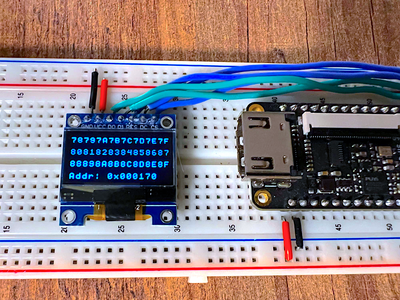
node scripts/assembler.js programs/counter.progLooking at the resulting bin file in a hex editor we can see it outputted the following:
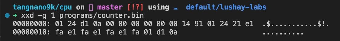
You can see our program starts off with 4 bytes, then we jump to line 10 (or 0a) we then get 6 bytes padding until address 10 where we have the rest of our program. Total size of our program is 26 bytes.
To write this to the tang nano you can run from the terminal:
openFPGALoader -b tangnano9k --external-flash ./programs/counter.binOr if you are using the Lushay Code extension in VsCode you can define a project file, for example called cpu.lushay.json like follows:
{
    "name": "cpu",
    "includedFiles": [
        "flash.v",
        "screen.v",
        "text.v",
        "top.v",
        "cpu.v"
    ],
    "constraintsFile": "tangnano9k.cst",
    "externalFlashFiles": [
        "programs/counter.bin"
    ],
    "synthGowinOptions": ["-noalu", "-nowidelut", "-nolutram", "-nodffe"],
    "nextPnrGowinOptions": ["--enable-globals", "--enable-auto-longwires"]
}
This defines how to build our project as-well as the external flash files we may want to program to our tang nano board. With this file created you can run the toolchain to both build and program the tang nano as-well as write the external flash file. Both of these operations can be found by clicking the "FPGA Toolchain" button.
If you are using the toolchain manually (without the Lushay Code extension) then you can create a make file like the following to build and program the tang nano:
BOARD=tangnano9k
FAMILY=GW1N-9C
DEVICE=GW1NR-LV9QN88PC6/I5

all: cpu.fs

# Synthesis
cpu.json: top.v text.v screen.v flash.v cpu.v
	yosys -p "read_verilog screen.v flash.v text.v cpu.v top.v; synth_gowin -noalu -nowidelut -nolutram -nodffe -top top -json cpu.json"

# Place and Route
cpu_pnr.json: cpu.json
	nextpnr-gowin --json cpu.json --write cpu_pnr.json --enable-auto-longwires --enable-globals --freq 27 --device ${DEVICE} --family ${FAMILY} --cst ${BOARD}.cst

# Generate Bitstream
cpu.fs: cpu_pnr.json
	gowin_pack -d ${FAMILY} -o cpu.fs cpu_pnr.json

# Program Board
load: cpu.fs
	openFPGALoader -b ${BOARD} cpu.fs -f

# Generate Font
font: font.hex
font.hex:
	node ./scripts/generate_font.js

# Cleanup build artifacts
clean:
	rm cpu.fs

.PHONY: load clean test
.INTERMEDIATE: cpu_pnr.json cpu.json
No matter how you run it, you should now see the LEDs on the tang nano counting up, just like in our first project. You should also be able to use the reset button to restart the program from line 0.
Creating Another Program
Now some people would say the article is already long enough, we have already implemented an instruction set, a CPU module, an assembler and our own first program and we should probably wrap up.
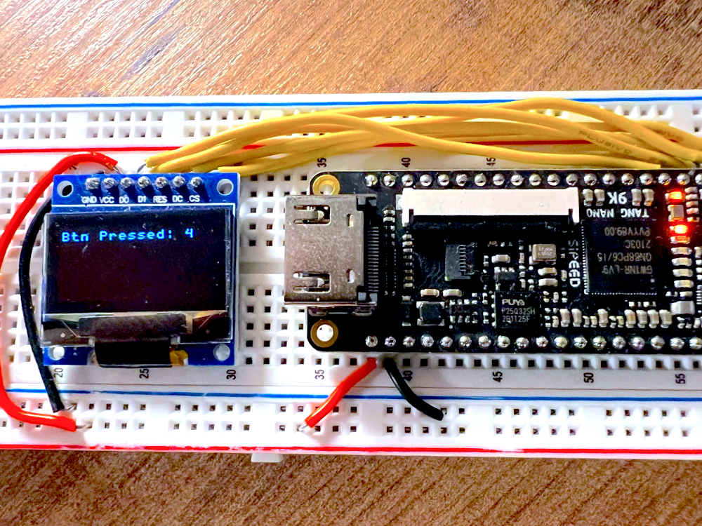
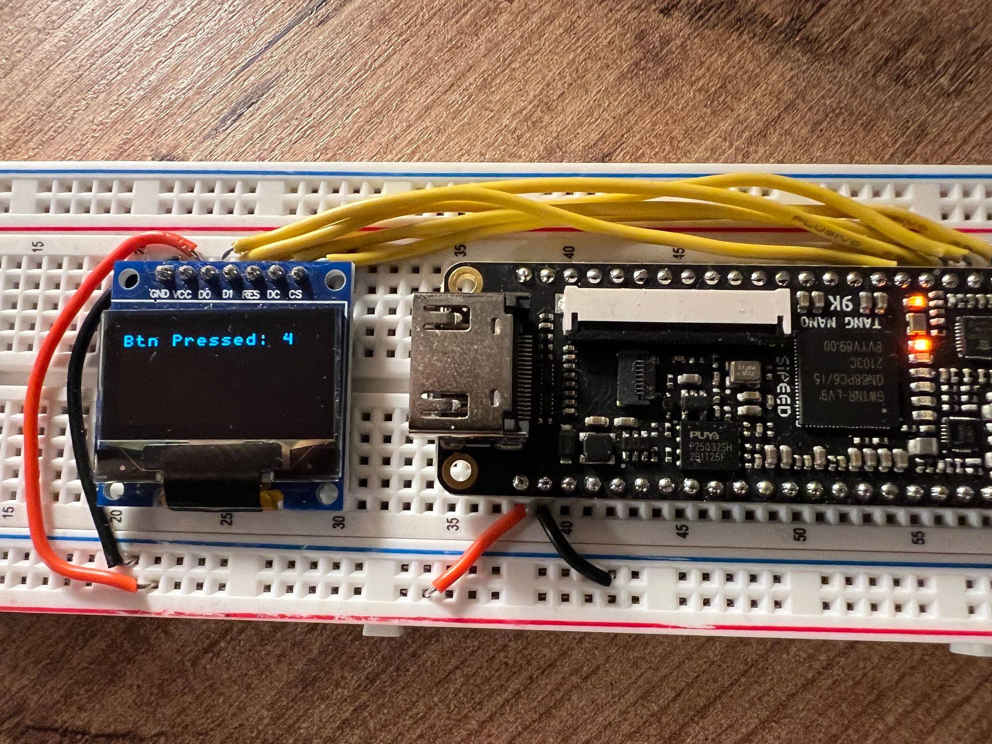
But I can't help create a second program, to showcase how versatile our little language is. Let us create another file in our programs folder called btn_counter.prog. Here we will create a program that prints to the screen `btn pressed: ` and the number of times the button has been pressed.
This will showcase both working with the screen, as-well as recieving input from the button.
CLR AC      ; screen pos stored in ac
PRNT 42h    ; 'B'
ADD 1       ; inc screen pos
PRNT 74h    ; 't'
ADD 1       ; inc screen pos
PRNT 6eh    ; 'n'
ADD 2       ; inc screen pos
PRNT 50h    ; 'P'
ADD 1       ; inc screen pos
PRNT 72h    ; 'r'
ADD 1       ; inc screen pos
PRNT 65h    ; 'e'
ADD 1       ; inc screen pos
PRNT 73h    ; 's'
ADD 1       ; inc screen pos
PRNT 73h    ; 's'
ADD 1       ; inc screen pos
PRNT 65h    ; 'e'
ADD 1       ; inc screen pos
PRNT 64h    ; 'd'
ADD 1       ; inc screen pos
PRNT 3ah    ; ':'
ADD 2       ; inc screen pos
STA C       ; c stores screen pos
CLR AC
JMPZ 60
We start off by printing the message Btn Pressed: to the screen, each time incrementing ac to increment the screen position before printing the next character. We store the final position, where we will want the number to be written to into the c register and then jump to line 60.
.org 60
CLR AC
ADD 30h     ; '0'
ADD A       ; a stores click count
STA B       ; b stores character to print
CLR AC
ADD C       ; load screen pos
PRNT B      ;
CLR BTN     ; Clear AC if btn pressed
JMPZ 80     ; if button is pressed jump down
CLR AC
JMPZ 60     ; button is not pressed reprint
At line 60 we clear the ac register in-order to load the a register which holds the current click counter, we also add 30 hex to convert the decimal number to ASCII. This works great up to 9, since ascii character 0x30 is "0" and 0x31 is "1" and so on. So our program will work up to nine, but that's ok to me for this example.
Once we have the ASCII char we want to print we store it in the b register since we need to put the character index into ac in-order to print. We do this by loading in the c register which is where we stored the char index.
With the char index set we print out the character we put in b and then run CLR BTN this will clear ac only if the button is pressed. We can combine this with a JMPZ which will only jump if ac is zero, so essentially we will only jump if the button is pressed. This allows us to branch to like 80 if the button is pressed, otherwise we loop back to line 60.
At line 80 we simply increment the a register which stores the click counter:
.org 80
CLR AC
ADD A       ; load current count
ADD 1       ; increment count
STA A       ; store updated count
CLR AC
JMPZ 100    ; jump to 100 for debounce
After incrementing A we jump to line 100 to wait for the button to be released, so that we only increment the button once per click.
.org 100
CLR AC
ADD 1       ; load 1 into AC
CLR BTN     ; clear if button is pressed
JMPZ 100    ; if button is still pressed loop
CLR AC
JMPZ 60     ; if button is not pressed reprint
At line 100, we set ac to 1 and then clear it only if the button is pressed. If the button is still pressed we loop back to 100 to try again. Once the button is released it will skip this jump and we can clear the ac register to jump back to 60 to print the new value.
You can compile this new program by running:
node scripts/assembler.js programs/btn_counter.progAnd then you can program it to the tang nano manually or by adding this to the cpu.lushay.json file under externalFlashFiles like our previous program.
Flashing it to the external flash you should now see our same FPGA core, running a completely different program, counting everytime we click on the button and printing it to the screen.
Conclusion
In this article we covered building a basic yet useable CPU and instruction set, and even covered writing a mini assembler to convert our programs into bytecode. Even though our instruction set is very simple, it gives a good starting point from which you can explore new concepts and take it much further.
For example after using this instruction set, I wanted to add a command to increment a register in-place without having to load it into the accumulator. Or you may interface other hardware into your processor, like maybe have memory mapped to UART, you may want to create a larger register to act as general purpose RAM for writing results back to memory instead of just the 4 main registers, etc.. I hope this inspires you to create your own instruction set and further explore this topic.
Like always, all the code for this project can be found in our github examples repo here.
If you would like to get any of the hardware from this article you can visit our store page here.
Thank you for reading, this isn't our last episode but it is definitely a milestone of ours, and we appreciate all the support we have been getting from the community.
If you have any questions feel free to leave them down below in the comments section or you can reach out on twitter @LushayLabs