
Some projects require having multiple modules use a common resource. This could be for a number of reasons like the common device might be an external peripheral (e.g. sensor / storage device) or it may be an expensive module so it might be to save on internal resources. Whatever the reason for doing this, special care needs to be taken when sharing resources to make sure the different modules don't interfere with each other.
In this article we will be taking a look at multiple sharing methods, when to use them and a how you can implement them.
The Problem
Before we take a look at solutions it's important to understand what problem we are trying to solve. Think of an example with two modules that need to write / read data from the external flash IC.
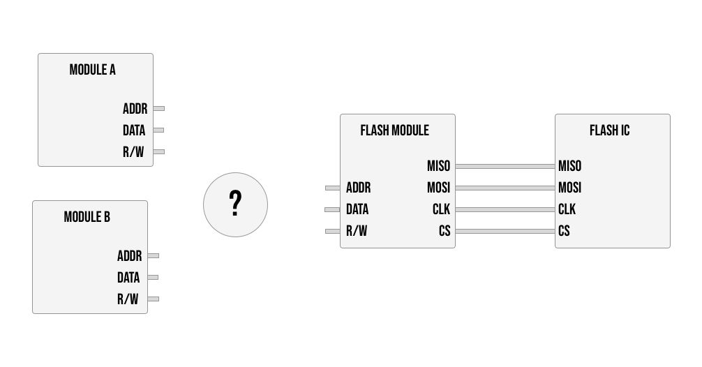
Simply OR-ing the connections from the two modules together will result in the flash module receiving a 1 if any of the modules send a high signal. So if module A would send address 10101 and module B would send 01010 at the same time the flash module would receive 11111 essentially corrupting the communication. This electrical interference would result in neither of the modules being able to perform correctly.
Now in this case we can't simply duplicate the flash module since externally we only have a single flash IC, but even internally there are times where it would be too expensive to duplicate (in terms of internal registers and LUTs) and to fit your design you need to have multiple modules reuse a component.
To make the above example work we need a way to wire the two modules up so that at most only 1 is using the flash module at a time.
Some Options
Choosing a solution depends on the specific requirements of the system you are building, some solutions are more lightweight while others are more robust. We can divide the multiple options into two main groups, federated access and unfederated access. Basically whether or not we need a separate module to control the flow or not.
Unfederated Access
In cases where the access is basic / predictable or cases where you only have two modules sharing a resource you can get away with wiring them up (effectively OR-ing the signals together) and you rely on a simple mechanism to make sure both devices don't use the device at the same time.
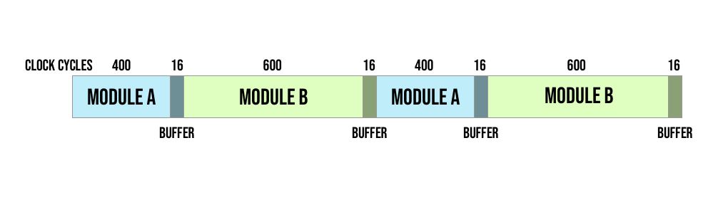
One way to do this is by using time (or a counter) and dividing up the time in advance between them. For example you can say each module gets 800 clock cycles and they can each have a counter to keep track of when it is their turn to use the device, idling during the other module's turn.
Something to look out for though is that you need to make sure the other module finished their current transaction before starting, so if it isn't exactly aligned you may need to add a buffer between modules to make sure there is no overlap. For example if a module's procedure takes 12 clock cycles, then you should have a buffer at the end of that module's turn of 11 clock cycles where they can't request but if they are in the middle of an operation they can finish.
This is a good solution when you need constant access from multiple devices, but what about a situation where we have one system always using the device and another only sometimes requires the device. For example if we are building a game, we may have one module which loads in a new level, and another module which runs every frame to pull data for rendering.
Loading level data is a large operation but it only happens once in a while (e.g. when you finish a level). Dividing the clock time between them would result in wasting a lot of time. If you gave it a large / equal share of the time it means most clock cycles would go unused, and if you gave it a very little share to minimize this effect, then when it does have to load a level it would take a long time being a heavy operation.
A better solution for this kind of situation is to have one module have priority over the other. The way this works is the level loader would act as the master device and would decide when it needs the shared resource or when it can be used by the other module.
You can accomplish this by the level loader having an extra wire to signify it wants to use the shared resource. When the wire goes high the secondary device would idle and wait before sending any other commands to the shared resource. Here too the master device might need to wait a few extra clock cycles to make sure if the secondary module was in the middle of a command that it finishes.
Now whenever loading a new level the level loader would gain full control of the memory making loading faster, and the rest of the time the rendering code would have full control not wasting extra time on the level loader.
This solution provides good performance but it only works if you have two devices, sharing with 3 or more devices using this signaling method requires more advanced handling which we will cover under federated access.
I brought these to examples as a way to illustrate that each use-case might be different and based on the specifics there might be a variation that works better. The main take away is you can get away with not adding a new module to handle access if you have some built in method for making sure they don't use the resource at the same time. This can be done with time slicing, signaling or things like that.
Federated Access
For more complex situations, like if the time each module will access the shared resource is less predictable or you have many modules sharing the resource, the best option is to have a standalone module to manage the resource sharing.
This kind of module has a few different names like an arbiter / controller / scheduler but the main idea is to implement a system where modules can request to use a shared resource and it is up to the controller to accept these requests and decide who is currently granted the resource using some kind of logic.
A basic example of this is a queuing system or a first in first out approach. In this approach the controller implements a queue and every module that wants to use the shared resource gets added to the queue. Then based on the order of the queue one module at a time will be granted the resource, once done they are removed from the queue and the next in line gets their turn.
This can be made more complex with prioritization logic, where certain modules will be put into a higher priority queue which is processed first. You may also want to add logic for when a module is allowed to request access, for example you may not allow a prioritised module to ask twice in a row allowing for other resources to also get scheduled.
And also you can control if each time a module is given access if it is limited to a single command or if they can hold the access for multiple commands. Allowing for multiple commands allows you to create semaphores which is required for handling critical sections that require atomic operations (or mutually exclusive operations).
An example of this could be you have a system where two modules increment the same memory address. For instance if you are building a router with 2 ethernet ports and you have a module for each port and you want to store the total bandwidth over both.
The problem with incrementing from memory is that it is essentially 2 operations, you need to read the current value and then rewrite the new value with the addition. If your controller doesn't allow 1 module to complete both of these steps in a single go, the value in memory can get trampled losing data. If for example the current total bandwidth is 12MB and each of the two port modules wants to add 1MB, if the controller schedules it as follows:
- Read current total Module A (value 12)
- Read current total Module B (value 12)
- Write new total Module A (value 13)
- Write new total Module B (value 13)
The both modules will receive 12MB as the current value and then both will write 13MB back (when the real value is 14MB). This ordering isn't that far fetched also, with a queue system, module B could already be in the queue before module A is able to finish their first operation and requests again.
In the above example you would need a controller which allows A to not release control of the shared memory until after both reading and writing the new value making the increment operation atomic.
With all that being said I think we can get into some implementation. In this article we will be creating a controller for federated memory access so that three modules can share the same memory.
The Implementation
Before we get into the actual controller, we need a shared resource. For this tutorial let's create a module to act as our shared storage. Arbitrarily let's make each position in memory be 4 bytes long (or 32-bits) and let's make there be 256 positions so that the address fits in a single byte.
To do this create a new file called shared_memory.v with the following:
`default_nettype none

module sharedMemory
(
    input clk,

    input [7:0] address,
    input readWrite,
    output reg [31:0] dataOut = 0,
    input [31:0] dataIn,
    input enabled
);

endmodule
As inputs we have the clock an 8-bit address line, a bit called readWrite which tells us if we are currently reading or writing (1 = read and 0 = write). After that we have two 32 bit registers, one for data out or data being read from memory, and one for data in which is data being written to memory.
The last input is an enable pin to tell the shared memory we are performing an action currently. There are some clock cycles where we both don't want to write or read, so this extra wire will tell it we are now performing an operation otherwise the shared memory can be idle.
Next let's create the storage itself inside:
reg [31:0] storage [255:0];
integer i;
initial begin
    for (i = 0; i < 256; i = i + 1) begin
        storage[i] = 0;
    end
end
The first line creates our memory called storage which like we said has 256 positions each of which with 32-bits. The rest of the lines are just to initialize the value of the memory to 0 and is not synthesized as part of the actual bitstream.
Finally the actual logic of the module:
always @(posedge clk) begin
    if (enabled) begin
        if (readWrite) begin
            dataOut <= storage[address];
        end
        else begin
            storage[address] <= dataIn;
        end
    end
end
Basically we wait for the enable pin to go high, then we perform an operation on every clock cycle, if the readWrite flag is high, we read the 32-bits stored at the requested address and store it in dataOut and if the flag is low we write dataIn into memory at the requested address.
To use this module you would basically need to set the address, readWrite flag and dataIn input (for write operations) and then enable the memory. In this design both read and write operations take a single clock cycle, so when enabled one could change all the inputs on each clock cycle to perform a different operation.
This memory module is a single port memory, meaning it expects only a single "user" at a time. So if we have multiple modules relying on this memory we need to synchronise between them on our own. So let's now start building our controller.
The Controller
The type of arbiter we will be making is a basic queue based controller where up to 3 modules can request access to the shared resource and we will allow for multiple commands to be performed before releasing.
To get started let's create a new file called controller.v with the following empty module:
`default_nettype none

module memController
(
    input clk,

    input [2:0] requestingMemory,
    output reg [2:0] grantedAccess = 0,

    output enabled,
    output [7:0] address,
    output [31:0] dataToMem,
    output readWrite,

    input [7:0] addr1,
    input [7:0] addr2,
    input [7:0] addr3,

    input [31:0] dataToMem1,
    input [31:0] dataToMem2,
    input [31:0] dataToMem3,

    input readWrite1,
    input readWrite2,
    input readWrite3
);

endmodule
The first 3 ports are the actual ports required to create the arbiter, the rest of the connections are to actually control the bus to the shared memory. Basically we have 3 input bits called requestingMemory, one for each module that wants to use the shared resource and we have an output called grantedAccess which will store the bit of the module who is currently in control.
So for example the first module will get bit 0 the second bit 1 and the third bit 2. requestingMemory can hold values like the following:
3'b011meaning that both module 1 and module 2 are requesting the shared resource and module 3 is not. The output grantedAccess on the other hand will only have a single bit active at a time. So for example if module 2 is currently the module in control of the shared resource then grantedAccess will be:
3'b010The next 4 ports comprise the output bus to the shared resource, you can notice that we don't include dataFromMem here as all modules can share those lines since there is only a single driver (the shared memory) as opposed to dataToMem where we have 3 drivers (the 3 modules requesting access) so they need to be muxed.
The rest of the ports are just the different options we can connect to the output, so for example addr1 is the address from module 1 and addr2 is the address from module 2 and so on. The same for dataToMem and the readWrite flag. Basically based on who is granted access we will connect the corresponding modules inputs to the outputs going to the shared memory.
So our module has two roles, one is to decide who is granted access, and the other role is to connect the wires based on who has access acting as the bus controller.
Just as a side note, these two roles can be separated, so you can have a more general purpose arbiter which only has the first 3 ports here, so it only outputs who is currently grantedAccess based on the requests, and then have a separate module which takes that info and controls the connection to the shared memory.
Next let's create some registers inside:
reg [(3*4)-1:0] queue = 0;
reg [2:0] currentlyInQueue = 0;
reg [1:0] queueNextIndex = 0;
reg [1:0] queueCurrIndex = 0;
We start by creating a register for our queue, we use 3 bits to store a module number like grantedAccess (so each bit represents a different module) and we make 4 places as we need at least 3 spaces and it's better to have a power of 2 so that the index registers will roll over automatically making them circular.
The next register currentlyInQueue will store whether or not one of the modules is already in the queue. This is in the format of requestingMemory where each bit is a different module and they can all be 1 at the same time.
Finally to implement a circular fifo queue we need to indices, one for each end of our queue. The first index is queueNextIndex which represents the next index where we should place a value, this is the end of our queue, and we have queueCurrIndex which is the first value in the queue (the one we will be giving access to) so they represent the two edges of the queue.
When we insert a new value into the queue we increment queueNextIndex and when we use a value from the beginning of the queue we increment queueCurrIndex. If the two indices are equal it means the queue is empty, and because we chose a power of 2 as the queue size we don't need to handle wrapping around to the beginning in our circular queue, it will happen automatically.
Next let's add two "helper" wires which we can use to simplify the modules task:
wire [2:0] requestsNotInQueue;
wire [2:0] nextInLine;
requestsNotInQueue is basically the opposite of currentlyInQueue just with an extra check to make sure they are requesting access, for example module 2 might not be in the queue, but it may not want to be in the queue so we filter for only requesting modules. nextInLine will store one out of the possible 3 modules requesting access as we can only handle 1 request at a time.
We can already assign these two wires as follows:
assign requestsNotInQueue = (requestingMemory & ~currentlyInQueue);
assign nextInLine = requestsNotInQueue[0] ? 3'b001 :
	requestsNotInQueue[1] ? 3'b010 : 3'b100;
assign enabled = grantedAccess[0] | grantedAccess[1] | grantedAccess[2];
Like I mentioned we flip currentlyInQueue and AND it with the modules requesting access to get a list of modules not in the queue but that want to be in the queue.
nextInLine is simply the first bit that is currently requesting and not in the queue. Again this is because in our module we can only add a single request to our queue per clock cycle, so at each iteration we need only a single requester, this is what is stored in nextInLine.
Finally enabled is high if control to the shared resource is currently granted to one of the 3 modules, we OR all the bits together, this is the same as checking whether it doesn't equal zero.
Now let's handle adding someone to the queue:
always @(posedge clk) begin
    if (requestsNotInQueue != 0) begin
        queue[(queueNextIndex * 3)+:3] <= nextInLine;
        currentlyInQueue <= currentlyInQueue | nextInLine;
        queueNextIndex <= queueNextIndex + 1;
    end
end
On each clock cycle we see if there are modules requesting access that are still not in the queue using our helper wire we just hooked up. If there is we place nextInLine which is one of the three modules (e.g. 3'b010 for module 2) and we place it in the queue at the next available index.
The next line sets the module's corresponding bit in currentlyInQueue to 1 so that it won't be added again to the queue and finally we increment queueNextIndex to point at the next available index where a request should be added.
Next let's add the code to remove a request from the queue when someone releases control, so in the same always block add the following:
else if (enabled && (requestingMemory & grantedAccess) == 0) begin
    grantedAccess <= 3'b000;
    queueCurrIndex <= queueCurrIndex + 1;
    currentlyInQueue <= currentlyInQueue & (~grantedAccess);
end
The first condition is if enabled is high, which is the same as saying, if access is currently being granted to someone. The second condition is to check that the person currently granted access is no longer requesting access. By ANDing the bit of the current module controlling the shared memory with the requests we isolate that specific bit, and then if it equals zero we know they released control.
So if we are currently granting access to someone and they have stopped requesting access, we will remove them from the queue by incrementing queueCurrIndex. We also set grantedAccess to zero removing the access from this module, and we unset the bit from currentlyInQueue corresponding to this module.
The reason this is in an else if, instead of happening in parallel, is because they both are setting values for currentlyInQueue which will cause verilog to take the last update if both were to happen losing data of a module being added to the queue. So we can either add a new module request to the queue or remove a request from the queue, not both at the same time.
The final section in our always block is to actually give access to the module at the start of our queue:
if (~enabled && queueNextIndex != queueCurrIndex) begin
    grantedAccess <= queue[(queueCurrIndex * 3)+:3];
end
So if we are currently not giving access to anyone, and the two indices for next available and current queue item are not equal (which would signify an empty queue) then we can give the next in line access.
This can happen in parallel to adding / removing module requests from the queue.
With that the only thing left to do here is to actually mux the wires to the shared memory based on who is currently grantedAccess. So at the bottom of our module (outside the always block) add the following:
assign address = (grantedAccess[0]) ? addr1 :
                 (grantedAccess[1]) ? addr2 :
                 (grantedAccess[2]) ? addr3 : 0;

assign readWrite = (grantedAccess[0]) ? readWrite1 :
                   (grantedAccess[1]) ? readWrite2 :
                   (grantedAccess[2]) ? readWrite3 : 0;

assign dataToMem = (grantedAccess[0]) ? dataToMem1 :
                   (grantedAccess[1]) ? dataToMem2 :
                   (grantedAccess[2]) ? dataToMem3 : 0;
For each of the ports we need to mux, we simply check which bit is currently high and based on that connect output to the corresponding modules input.
We should now have a working arbiter which will allow for up to 3 modules to share our memory module we created. Now before building an example let's create a testbench so that we can visually verify that the controller is working.
Testing Our Controller
To test our module and create a VCD file where we can visualize our module in action we can create a file called controller_tb.v with the following:
module test();
    reg clk = 0;

    always
        #1  clk = ~clk;

    initial begin
        #1000 $finish;
    end


    initial begin
        $dumpfile("controller.vcd");
        $dumpvars(0,test);
    end
endmodule
This creates a blank module with a clock that flips once per frame and we setup the simulation to end after 1000 frames. The last block will output anything defined in this module into a VCD file.
So next we only need to instantiate our controller and we will be able to test it:
reg req1 = 1, req2 = 1, req3 = 1;
wire [2:0] grantedAccess;
wire enabled;

wire [7:0] address;
wire [31:0] dataToMem;
wire readWrite;

reg [7:0] addr1 = 8'hA1;
reg [7:0] addr2 = 8'hA2;
reg [7:0] addr3 = 8'hA3;

reg [31:0] dataToMem1 = 32'hD1;
reg [31:0] dataToMem2 = 32'hD2;
reg [31:0] dataToMem3 = 32'hD3;

memController fc(
    clk,
    {req3,req2,req1},
    grantedAccess,
    enabled,
    address,
    dataToMem,
    readWrite,
    addr1,
    addr2,
    addr3,
    dataToMem1,
    dataToMem2,
    dataToMem3,
    1'b0,
    1'b1,
    1'b0
);
We go through creating all the registers and wires required to instantiate our controller. We won't really have modules using the shared memory, so in terms of address we will use a static address to simulate this, same for the data we will just hardcode a value.
Next to really test the requeing we need a way to simulate a module releasing access once granted and then to re-request access making it get re-added to the queue. We can do this by just adding a counter for example we will count 4 frames and then release the shared resource:
reg [1:0] counter = 0;
always @(posedge clk) begin
    if (enabled) begin
        counter <= counter + 1;
        if (counter == 2'b11) begin
            if (grantedAccess == 3'b001) begin
                req1 <= 0;
            end
            else if (grantedAccess == 3'b010) begin
                req2 <= 0;
            end
            else if (grantedAccess == 3'b100) begin
                req3 <= 0;
            end
        end
    end
    else begin
        counter <= 0;
        req1 <= 1;
        req2 <= 1;
        req3 <= 1;
    end
end
So when the enabled wire is high, we count up four frames and then set the corresponding request bit to zero. Otherwise in-between when modules are currently granted access we reset all request bits to 1.
We could have shortened this by having the request bits be a single register and using the same method as we used in the controller for setting unsetting currentlyInQueue, but I think this allows for better visualization when viewing the VCD file as we can see each bit separated on its own line.
You can compile and run this with the following commands:
iverilog -o controller_test.o -s test controller.v controller_tb.v
vvp controller_test.o
You should then see a VCD file called controller.vcd. Looking through this file we can see that everything seems to be working great:
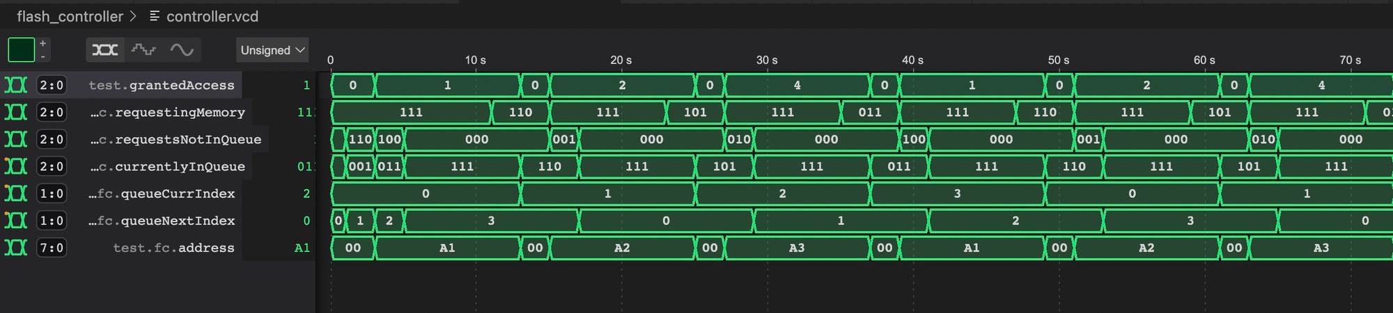
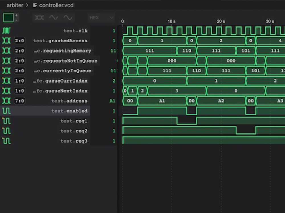
On the first line we can see that each module receives the resource for 4 frames and we can see the order repeating and that each module is getting it's time on the resource. On the last line we can see the address coming out from the controller and we see it match the hardcoded address for each of our 3 input modules.
In the middle you can see how it adds each requesting module to the queue 1 at a time and how the indices wrap around giving us an endless circular queue.
With everything working as expected we can now move on to actually running it on the tang nano.
Using the Shared Memory
We created a module already which holds are shared memory, and now we have the arbiter ready to allow for sharing, the last piece we need is the modules who will be using the memory.
Let's create a module which increments a value in memory, we can use this to double check we don't get any race conditions and that our controller can be used as a semaphore.
To get started let's create a file called memory_inc.v with the following module:
module memoryIncAtomic (
    input clk,
    input grantedAccess,
    output reg requestingMemory = 0,
    output reg [7:0] address = 8'h18,
    output reg readWrite = 1,
    input [31:0] inputData,
    output reg [31:0] outputData = 0
);

endmodule
We want this module to increment a value in memory by 1 once a second. To interface with our controller we have an input for when this module has been granted control of the shared resource and we have an output bit requestingMemory to signal that we are requesting control of the shared resource.
Other then that we have outputs for the desired address, read/write flag and output data to memory and then we have an input register which will have the data read from memory.
To start off with we can create a counter to count if a second has passed:
reg [24:0] counter = 0;
always @(posedge clk) begin
    if (grantedAccess)
        counter <= 0;
    else if (counter != 25'd27000000)
        counter <= counter + 1;
end
We reset the counter whenever we are in control, and once we release control we start counting stopping when we reach 27,000,000 clock cycles which equals 1 second.
Next we will need a state machine so let's define our states:
reg [1:0] state = 0;

localparam STATE_IDLE = 2'd0;
localparam STATE_WAIT_FOR_CONTROL = 2'd1;
localparam STATE_READ_VALUE = 2'd2;
localparam STATE_WRITE_VALUE = 2'd3;
The first state is the idle state here we are waiting for a second to pass, once we have waited a second we will request control, but then we need to wait for the controller to grant us access. This is what we will do in the second state, once in control of the shared resource we can read the current value and then write the new value back to memory.
The implementation of these steps looks like this:
always @(posedge clk) begin
    case (state)
        STATE_IDLE: begin
            if (counter == 25'd27000000) begin
                state <= STATE_WAIT_FOR_CONTROL;
                requestingMemory <= 1;
                readWrite <= 1;
            end
        end
        STATE_WAIT_FOR_CONTROL: begin
            if (grantedAccess) begin
                state <= STATE_READ_VALUE;
            end
        end
        STATE_READ_VALUE: begin
            outputData <= inputData + 1;
            state <= STATE_WRITE_VALUE;
            readWrite <= 0;
        end
        STATE_WRITE_VALUE: begin
            requestingMemory <= 0;
            state <= STATE_IDLE;
            readWrite <= 1;
        end
    endcase
end
Like mentioned, the first state waits for the counter to reach 1 second, we then move to requesting control of the memory and set the readWrite flag to 1 to signify we want to read data.
In the second state we wait for grantedAccess to go high, meaning we have received control and we then move onto the next state where we will store the value returned from memory (over inputData) incremented by 1 into outputData. Besides for that in the next state we also set the readWrite flag to zero to signify that now we want to write the data we put on outputData to memory.
In the final state we basically just wanted another clock cycle to give the memory module a chance to write the data and then we can go back to the idle state releasing the shared resource by un-requesting the memory.
While here we can create a second module, exactly like this one except only for reading:
module memoryRead (
    input clk,
    input grantedAccess,
    output reg requestingMemory = 0,
    output reg [7:0] address = 8'h18,
    output reg readWrite = 1,
    input [31:0] inputData,
    output reg [31:0] outputData = 0
);

    reg [24:0] counter = 0;
    always @(posedge clk) begin
        if (grantedAccess)
            counter <= 0;
        else if (counter != 25'd27000000)
            counter <= counter + 1;
    end

    reg [1:0] state = 0;

    localparam STATE_IDLE = 2'd0;
    localparam STATE_WAIT_FOR_CONTROL = 2'd1;
    localparam STATE_READ_VALUE = 2'd2;

    always @(posedge clk) begin
        case (state)
            STATE_IDLE: begin
                if (counter == 25'd27000000) begin
                    state <= STATE_WAIT_FOR_CONTROL;
                    requestingMemory <= 1;
                    readWrite <= 1;
                end
            end
            STATE_WAIT_FOR_CONTROL: begin
                if (grantedAccess) begin
                    state <= STATE_READ_VALUE;
                end
            end
            STATE_READ_VALUE: begin
                outputData <= inputData;
                state <= STATE_IDLE;
                requestingMemory <= 0;
            end
        endcase
    end
endmodule
Exactly the same just we only read and outputData is not meant to go to the memory module, but rather to give the other modules the current value so we can display it.
With that done we can now create our top module connecting all our other components.
Connecting Everything Together
We can start with a constraints file, we will again be using our screen and text modules to display the value in memory. Create a file called tangnano9k.cst with the following:
IO_LOC "clk" 52;
IO_PORT "clk" PULL_MODE=UP IO_TYPE=LVCMOS33;

IO_LOC "ioCs" 36;
IO_PORT "ioCs" IO_TYPE=LVCMOS33 PULL_MODE=DOWN DRIVE=8;
IO_LOC "ioDc" 39;
IO_PORT "ioDc" IO_TYPE=LVCMOS33 PULL_MODE=DOWN DRIVE=8;
IO_LOC "ioReset" 25;
IO_PORT "ioReset" IO_TYPE=LVCMOS33 PULL_MODE=DOWN DRIVE=8;
IO_LOC "ioSdin" 26;
IO_PORT "ioSdin" IO_TYPE=LVCMOS33 PULL_MODE=DOWN DRIVE=8;
IO_LOC "ioSclk" 27;
IO_PORT "ioSclk" IO_TYPE=LVCMOS33 PULL_MODE=DOWN DRIVE=8;
This holds the clock and all wires for the screen. Next we can create a file called top.v with the following:
`default_nettype none

module top
#(
  parameter STARTUP_WAIT = 32'd10000000
)
(
    input clk,
    output ioSclk,
    output ioSdin,
    output ioCs,
    output ioDc,
    output ioReset
);
    wire enabled, readWrite;
    wire [31:0] dataToMem, dataFromMem;
    wire [7:0] address;

    wire req1, req2, req3;
    wire [2:0] grantedAccess;
    wire readWrite1, readWrite2, readWrite3;
    wire [31:0] currentMemVal, dataToMem2, dataToMem3;
    wire [7:0] address1, address2, address3;

    wire [9:0] pixelAddress;
    wire [7:0] textPixelData;
    wire [5:0] charAddress;
    reg [7:0] charOutput;

    screen #(STARTUP_WAIT) scr(
        clk,
        ioSclk,
        ioSdin,
        ioCs,
        ioDc,
        ioReset,
        pixelAddress,
        textPixelData
    );

    textEngine te(
        clk,
        pixelAddress,
        textPixelData,
        charAddress,
        charOutput
    );

    memController fc(
        clk,
        {req3,req2,req1},
        grantedAccess,
        enabled,
        address,
        dataToMem,
        readWrite,
        address1,
        address2,
        address3,
        0,
        dataToMem2,
        dataToMem3,
        readWrite1,
        readWrite2,
        readWrite3
    );

    sharedMemory sm(
        clk,
        address,
        readWrite,
        dataFromMem,
        dataToMem,
        enabled
    );
endmodule
This might look like a lot but it is just because we are connecting a number of components here. The ports our module receive are simply the wires to drive the screen and the main clock signal. The first group of wires/registers are for driving the shared memory. The next group is all the wires for the controller, and the final group of wires and registers is for the screen and text engine.
After that we simply add instances for our screen driver, text engine, controller and shared memory.
Next we can create instances of our memory read / memory inc modules:
memoryRead mr (
    clk,
    grantedAccess[0],
    req1,
    address1,
    readWrite1,
    dataFromMem,
    currentMemVal
);

memoryIncAtomic m1 (
    clk,
    grantedAccess[1],
    req2,
    address2,
    readWrite2,
    dataFromMem,
    dataToMem2
);

memoryIncAtomic m2 (
    clk,
    grantedAccess[2],
    req3,
    address3,
    readWrite3,
    dataFromMem,
    dataToMem3
);
Each one gets their own grantedAccess bit and request bit, and they have the other connections for the controller and from memory. At this stage we have 1 module reading from memory once a second, and another two modules each incrementing the same memory once a second.
The last step is just to display the value in memory so we can see it being incremented correctly:
wire [1:0] rowNumber;
assign rowNumber = charAddress[5:4];

genvar i;
generate
    for (i = 0; i < 8; i = i + 1) begin: hexVal
        wire [7:0] hexChar;
        toHex converter(clk, currentMemVal[(i*4)+:4], hexChar);
    end
endgenerate

always @(posedge clk) begin
    if (rowNumber == 2'd0) begin
        case (charAddress[3:0])
            0: charOutput <= "0";
            1: charOutput <= "x";
            2: charOutput <= hexVal[7].hexChar;
            3: charOutput <= hexVal[6].hexChar;
            4: charOutput <= hexVal[5].hexChar;
            5: charOutput <= hexVal[4].hexChar;
            6: charOutput <= hexVal[3].hexChar;
            7: charOutput <= hexVal[2].hexChar;
            8: charOutput <= hexVal[1].hexChar;
            9: charOutput <= hexVal[0].hexChar;
            default: charOutput <= " ";
        endcase
    end
end
We create a wire to extract the row number and we generate 8 hex converters to convert the 8 hex chars needed to represent our 32-bit value. The always block will check if we are on the first text row of the screen and if so output 0x followed by the 8 hex characters.
To make this work we also need to add our hex converter module, you can add this at the top / bottom of the same file top.v:
module toHex(
    input clk,
    input [3:0] value,
    output reg [7:0] hexChar = "0"
);
    always @(posedge clk) begin
        hexChar <= (value <= 9) ? 8'd48 + value : 8'd55 + value;
    end
endmodule
We won't go into this here, as it is a component we have already built in the past when we built the text engine, but if you would like to see any of the previous sections you can take a look here, and if you need any of the files for the screen / text or font files used from previous articles you can find them on our github here
Running our Project
Let's create a Makefile to build and program our test project:
BOARD=tangnano9k
FAMILY=GW1N-9C
DEVICE=GW1NR-LV9QN88PC6/I5

all: arbiter.fs

# Synthesis
arbiter.json: top.v shared_memory.v controller.v memory_inc.v screen.v text.v
	yosys -p "read_verilog top.v shared_memory.v controller.v memory_inc.v screen.v text.v; synth_gowin -noalu -nolutram -top top -json arbiter.json"

# Place and Route
arbiter_pnr.json: arbiter.json
	nextpnr-gowin --json arbiter.json --write arbiter_pnr.json --enable-auto-longwires --enable-globals --freq 27 --device ${DEVICE} --family ${FAMILY} --cst ${BOARD}.cst

# Generate Bitstream
arbiter.fs: arbiter_pnr.json
	gowin_pack -d ${FAMILY} -o arbiter.fs arbiter_pnr.json

# Program Board
load: arbiter.fs
	openFPGALoader -b ${BOARD} arbiter.fs -f

# Generate Font
font: font.hex
font.hex:
	node ./scripts/generate_font.js

# Generate Simulation
controller_test.o: controller.v controller_tb.v
	iverilog -o controller_test.o -s test controller.v controller_tb.v

# Run Simulation
test: controller_test.o
	vvp controller_test.o

# Cleanup build artifacts
clean:
	rm arbiter.fs font.hex controller.vcd

.PHONY: load clean test font
.INTERMEDIATE: arbiter_pnr.json arbiter.json controller_test.o
You can then run make font to generate the font (if you copied the scripts and fonts folder from our text engine) and then make load to compile everything and program the tang nano.
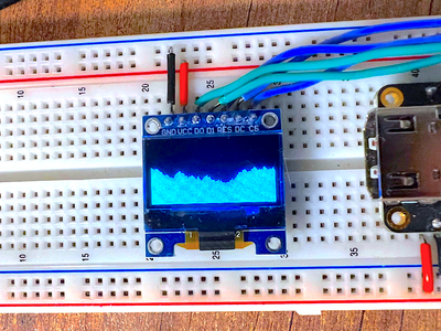
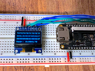
Running it should give you something like the following:
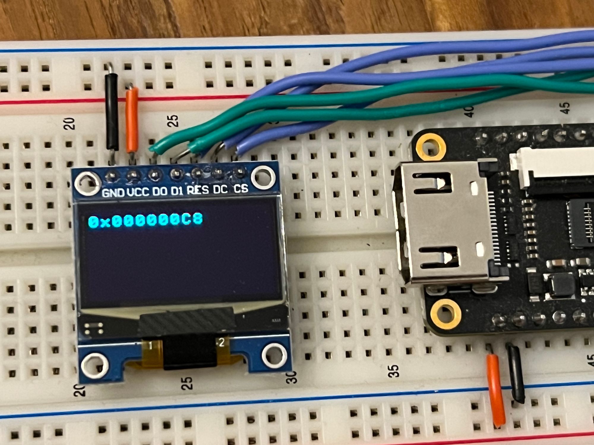
If you see it counting up by 2 every second then you know everything is working and there is no interference between our 3 modules and all of them are sharing a common memory module.
Conclusion
In this article we took a look at the problem of sharing resources and some ways to fix it, we also built a pretty robust controller to allow for resource sharing and for mutual exclusion. With that being said this can be taken further by adding more logic in terms of nextInLine or having multiple priority queues to allow for things like interrupts, etc.
I would like to thank you for reading, hope you enjoyed it.
Like always if you have any questions or comments you can leave them down below or contact us on twitter @LushayLabs.
All the source code for this series can be found on our github series page here.
If you would like to purchase any of the components used in this article and support the site you can visit our store here.
