
In this article we will be taking a look at generating pseudo-random numbers using an LFSR (Linear Feedback Shift Register) and look at how one can be used as part of a larger application.
The LFSR
An LFSR is a shift register like we have seen in previous articles, except that the bits besides shifting are also affected by the other bits in the register - this effect is what is referred to as the feedback.
There are multiple variations of LFSR but in this article we will be focusing on the most basic type the Fibonacci LFSR. In this type of LFSR the feedback only affects the first bit. So all bits get shifted up and the least significant bit is generated using the feedback of the current registers bits.
A basic example of a 5-bit LFSR:
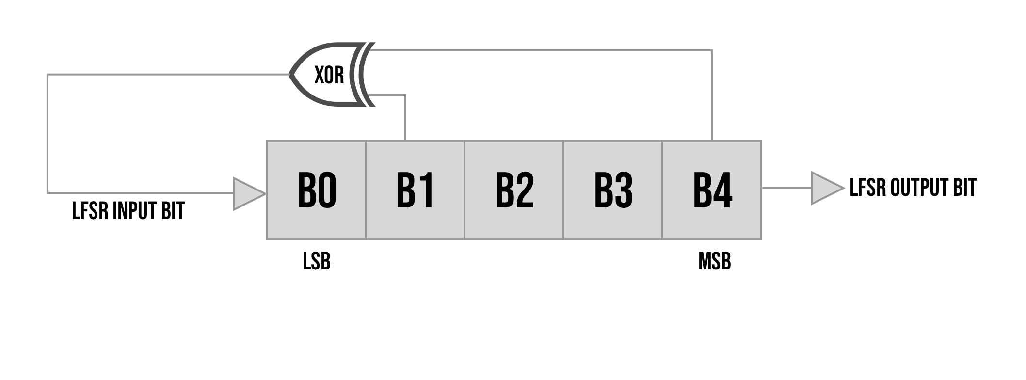
So in the example above on each clock cycle B4 is the output bit b0-b3 get shifted up and a new bit is generated by XOR-ing bit 4 and bit 1 this new bit gets inserted into b0.
The bits we choose for our feedback are called "taps", and not every arrangement of taps are good options. Since our new bit is generated by XOR-ing bits, if all bits were zero the system would be stuck in the zero state. XOR can be thought of as returning 1 if the number of 1s being XOR-ed is odd. Since all zeroes has zero 1s and shifting will just keep inputting a new zero we never get out of this state.
Another thing to consider, the entire equation is only based on the current state of the register there is no other state being used in the calculation, so as soon as the register rolls back to a number it already was on that will create a cycle. For example if we have an LFSR generating numbers from 1-16 but has an initial cycle of: 1, 4, 7, 14, 3, 5, 7, 14, 3, 5, 7
You can see that as soon as we had two ways of getting to 7 (both 4 generated a 7 as the next number and also a 5) we get stuck in a loop between the two numbers. All further cycles will just go between 7, 14, 3, 5 in an endless cycle.
The problem with these short cycles is that the LFSR can no longer generate any number in the range. If I have a 6-sided dice that can only be a 2 or a 4 it wouldn't really be considered a fair dice in the realm of numbers 1-6 as the probabilities for each number are not the same.
So when choosing taps we want to choose something that:
- Never generates all zeroes
- Generates a sequence that goes through all possible numbers
Luckily for us, we do not have to manually calculate optimal taps instead there are pre-calculated tables for max length taps. For example this site here has a precompiled list of max-length taps for LFSRs with 4-64 bits.
For example opening the file for 5-bit LFSRs like in the example above has the following options:
12
14
17
1B
1D
1E
Each of these is an optional tap set. The example above used the 12 option, these numbers are in hex, but converting 12 hex to binary provides:
10010Least significant bit to least significant bit, this means take bits index 1 and index 4 for the feedback and leave out index 0,2 and 3 like in this image:

But any of these options would produce a max-length sequence. Now that we have something that can generate a complete sequence of all numbers let us talk a little about the "random" part.
Pseudo Random
The LFSR produces a sequence which includes all the possible options, but that doesn't necessarily make it "random". For example if we are talking about a 3-bit LFSR, we can get all the numbers 1-7, but a 3-bit counter also produces all the numbers from 1-7 but it would hardly be random.
Taking a look at a counter's sequence:
1,2,3,4,5,6,7All numbers in this sequence have the same number of occurrences, but each number is just the previous number plus 1 making it to obvious of a relationship for us to call it unpredictable or random.
Now like with a deck of cards, the way can randomize the output is by shuffling. So let's shuffle this group of numbers into the following for example:
7, 6, 4, 1, 2, 5, 3One can now say that the sequence is random, because the order in which the numbers come out are no longer related to previous elements. The sequence is still not perfect as there are no duplicates, for example with rolling a dice I can roll a 4 and then roll another 4 before going through all the other options. But we can at least say it is as random as a deck of cards being randomly shuffled.
The problem with this solution is it requires something else to randomly shuffle the elements for it to really be random and it is hardware intensive to implement. To create such a system we would need to store each number of the sequence kind of like a 1-time pad so for example with a 32-bit LFSR we would need to store 2^32 -1 numbers over 4-billion 32-bit numbers or about 16GB of storage for 1 sequence, and we would even want sequences much longer then this.
So an LFSR is somewhere in-between a real shuffled sequence to a sequence with an obvious relation like a counter. The LFSR - when the taps are chosen correctly - produces all the numbers (except 0) in a sequence shuffled based on a non-obvious relation.
Starting with the seed value (initial value) of 1, let's the sequence given by this shift register will be:
binary | decimal
001 | 1
011 | 3
111 | 7
110 | 6
101 | 5
010 | 2
100 | 4
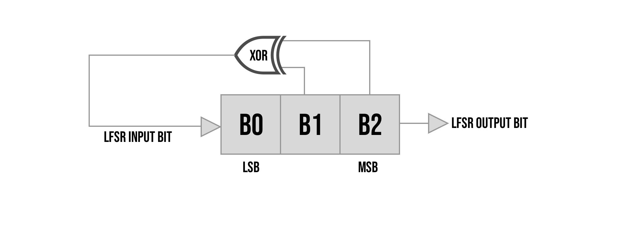
001 | 1Looking at this sequence you can see that we go through all the numbers before reaching back to 1 and that the sequence is shuffled. The reason we call this "pseudo-random" and not random is because there is a correlation between them, it can be said that the function for the first bit is:
b0 = b1 xor b2and that for the other bits the equation is simply:
b_i = b_(i-1)As each bit is simply shifted up. Since there is a correlation between the previous state and the next state with enough of the sequences outputs one could solve some math equations and work out which taps were chosen being able to predict future numbers in the sequence.
So it's not unpredictable, but the order has no meaningful meaning so we can say it is shuffled. With that said there are some things we can do to make it even better.
The first thing is to make the LFSR larger then the number we are using. For example if we need a 4-bit number and we use instead a 5-bit LFSR taking 4 bits at a time, we essentially doubled the number of times each number comes up allowing our sequence to have streaks of the same number like we mentioned that dice rolls have. We also get the ability to get 0 as a number, all the bits of an LFSR cannot equal zero but if you are reading only some of the bits then they can all equal zero.
In reality you usually want the LFSR to be much bigger (not just by one bit) and use a relatively small number of bits. Another way to make it better is to not reuse the same bits and to skip bits in-between numbers.
Each shift of the register you only get 1 new "random" bit. All the other bits are just shifted over which is like doubling. So in the case of the 3-bit LFSR if you wait 3-bits before taking another number then all of the new numbers 3-bits are completely unrelated to the bits of the previous number making it more random.
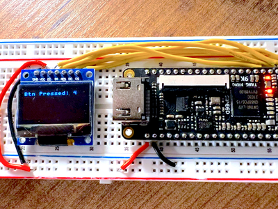
Finally if you let the LFSR run in the background essentially skipping generated bits and then let random actions like when a user pressed a button decide when to read the next number you are essentially adding in random like when shuffling bringing it closer to real random.
I think that is enough theory though let's get into building this.
The Implementation
Implementation wise it couldn't be any easier we just need a register with the number of bits we want in the LFSR and we need to connect some of the bits to the input of the first bit based on the taps we chose.
Taking our 5 bit LFSR from before we can create a simple verilog file like the following:
module lfsrTest (
    input clk,
    output reg randomBit = 0
);
  reg [4:0] sr = 5'b00001;

  always @(posedge clk) begin
    sr <= {sr[3:0], sr[4] ^ sr[1]};
    randomBit <= sr[4];
  end
endmodule
We seed the shift register with an initial value of 1 and on each clock pulse we shift the bits up and calculate the new input bit for b0 by XOR-ing bit 4 and bit 1 together. We then set the output register which holds the random bit to the value of b4 in our shift register (the bit we shifted off).
Running this would produce the following sequence:
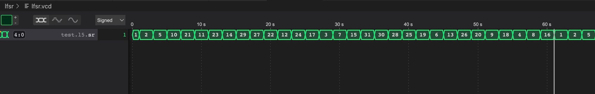
With five bits we have 2^5 options -1 removing the zero case we get a period of 31 numbers. And as you can see the order seems pretty random:
1,2,5,10,21,11,23,14,29,27,22,12,24,17,3,7,15,31,30,28,25,19,6,13,26,20,9,18,4,8,16Already looks pretty good but again there is some correlations where you can see the number just doubling because of the shift for example at the beginning or end of the sequence. Let's now take a look if we don't reuse bits and only take 3-bit numbers.
wire randomBit;
lfsrTest testLFSR (
  clk,
  randomBit
);
reg [2:0] tempBuffer = 0;
reg [1:0] counter = 0;
reg [2:0] value;

always @(posedge clk) begin
  if (counter == 3) begin
      value <= tempBuffer;
  end
  counter <= counter + 1;
  tempBuffer <= {tempBuffer[1:0], randomBit};
end
We start by creating a wire for the randomBit and creating an instance of our test LFSR connecting it to our wire. Next we can create a buffer to hold the bits as they are shifted off the LFSR and another register to count every time we got 3 new bits and a final register to store the value once ready.
Inside the clock loop we check for when the counter reaches 3 in which case we transfer the temp value into the value register. Other then that we always increment the counter and shift the new randomBit into our temp buffer shifting everything up.
Looking at the output of this we get the following:
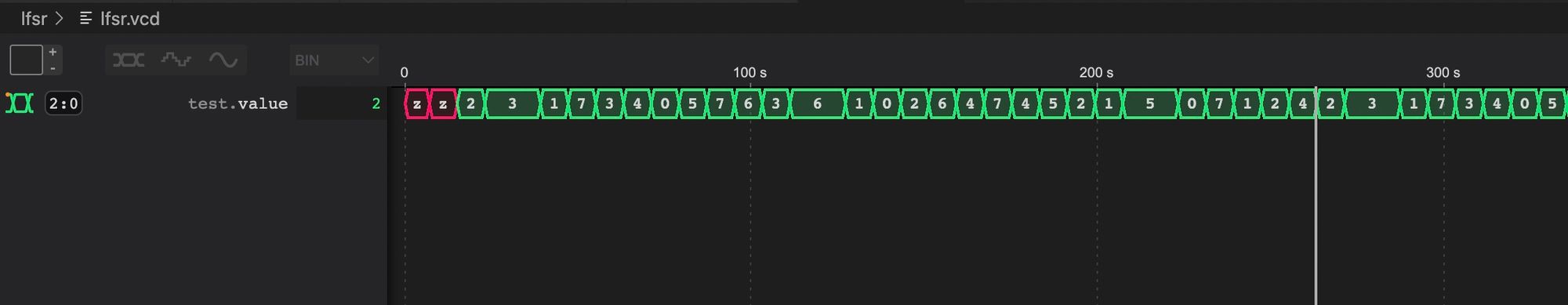
The first two numbers are not defined as we didn't initialize our registers with a value but it's ok since not all the bits are random there. Looking at the sequence now we get:
2,3,3,1,7,3,4,0,5,7,6,3,6,6,1,0,2,6,4,7,4,5,2,1,5,5,0,7,1,2,4Our sequence length is still 31 but now since we are reading smaller bit-sized numbers we have multiple duplicates of each number 4 to be exact since we left off two bits and 2^2 = 4. Except for 0 which there is only 3 since one of the options is when the LFSR equals all zeros which is not a valid case.
Another benefit here is you can see there are some streaks and also if you get a number for example a 2 you don't know the next number as it could be a 3,6,1 or 4 because of the multiple occurrences.
Adding the fact that you let it run at 27MHZ that means it goes through the whole cycle about 900,000 times a second or about 1 micro-second. If you only take a number based on for example user-input like a button press, a person can't reliably time their button presses to 1/31-th of a microsecond to get a specific number in the sequence making it pretty much random for most use-cases.
Before we start playing with LFSRs let's see how we can generalize our module so we don't need to create a new one for each different LFSR we add.
Generalizing the LFSR Module
The difference between all LFSRs of this type (fibonacci / external LFSRs) is the size of the register (num bits) the tap configuration, and some would say the initial seed.
Changing the seed doesn't change the sequence, it just changes where you start in the sequence, but we can say that this is another difference.
Other then that we still just need to create a register shift the bits over and calculate the new bit based on the taps chosen.
Let's create a file called lfsr.v with a module accepting these as parameters:
`default_nettype none

module lfsr
#(
  parameter SEED = 5'd1,
  parameter TAPS = 5'h1B,
  parameter NUM_BITS = 5
)
(
    input clk,
    output reg randomBit
);

  reg [NUM_BITS-1:0] sr = SEED;

endmodule
So far we just have our 3 parameters and we create a register of the desired size holding our seed value as it's initial value. The next step is the calculation each clock cycle:
wire finalFeedback;

always @(posedge clk) begin
  sr <= {sr[NUM_BITS-2:0],finalFeedback};
  randomBit <= sr[NUM_BITS-1];
end
We can start with a wire which will hold the feedback after the feedback calculation (XORs). We still haven't calculated it, but assuming we have it our always block looks pretty similar to before, shifting all the bits up 1 and putting our feedback bit into b0.
Now how do we XOR the bits from our taps to generate the final feedback bit. To do this we can simply go over all bits and either XOR them or XOR a zero, XOR-ing a zero doesn't affect the output, its like multiplying by one. So we will chain each bit with the value of the previous bit's feedback XOR-ed either with it or with a zero if it is not a tap. I think it will be more clear after looking at the code:
genvar i;
generate
  for (i = 0; i < NUM_BITS; i = i + 1) begin: lf
    wire feedback;
    if (i == 0)
      assign feedback = sr[i] & TAPS[i];
    else
      assign feedback = lf[i-1].feedback ^ (sr[i] & TAPS[i]);
  end
endgenerate
We create a generate block, which is a way to "generate" repetitive verilog code using loops instead.
So we loop over all the bits storing the current index inside i, we also name this loop lf (linear feedback) so that we will have a reference to access any wires or registers defined inside.
In each iteration of the loop we create a feedback wire and we connect it to one of two things. If we are on the first bit, there is no previous bit, so we simply take the current bit (sr[i]) AND-ed together with the same bit from the TAP parameter.
What this is doing is either evaluating to the value of current bit sr[i] if the TAP bit is 1, or making these two evaluate to zero if the TAP is not part of the XOR equation. By making it zero it won't affect the XOR operation.
For all the other bits we take the previous feedback and XOR it with the same AND equation to either make it a zero if it is not part of our XOR equation, or return the value of sr[i]. Taking this and XOR-ing it with the previous number will either update the feedback with the bit, or essentially pass the feedback from the previous bit forward without changing it if it is not related to the equation.
Finally we can connect the feedback from the final iteration to the wire we created finalFeedback:
assign finalFeedback = lf[NUM_BITS-1].feedback;With that we now have a fully working LFSR of any size and any tap configuration. To test it let's create a test bench so we can simulate a few different LFSRs so in a file called lfsr_tb.v:
module test();
  reg clk = 0;
  wire l1Bit, l2Bit, l3Bit;

  lfsr #(
    .SEED(5'd1),
    .TAPS(5'h12),
    .NUM_BITS(5)
  ) l1(
    clk,
    l1Bit
  );

  lfsr #(
    .SEED(5'd1),
    .TAPS(5'h1B),
    .NUM_BITS(5)
  ) l2(
    clk,
    l2Bit
  );

  lfsr #(
    .SEED(5'd1),
    .TAPS(5'h1E),
    .NUM_BITS(5)
  ) l3(
    clk,
    l3Bit
  );

  always
    #1  clk = ~clk;

  initial begin
    #1000 $finish;
  end

  initial begin
    $dumpfile("lfsr.vcd");
    $dumpvars(0,test);
  end
endmodule
Here besides for the boilerplate at the bottom for outputting the VCD file we are simply creating 3 LFSRs. They are all 5 bits with an initial seed of 1, but each has a different tap configuration.
Running this with:
iverilog -o lfsr_test.o -s test lfsr.v lfsr_tb.v
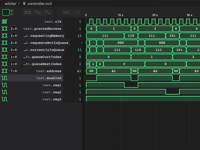
vvp lfsr_test.oWill create for us a VCD file, selecting the sr shift register from each of the 3 we created we see they all have the same period but are shuffled differently.
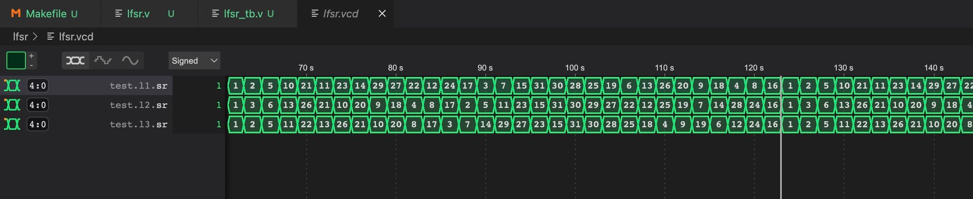
Again these tap values are simply taken from the corresponding file here which has tap values for max-length LFSRs of different sizes.
With this working, let's now make a simple project to see it in action.
Graphing the Random Values
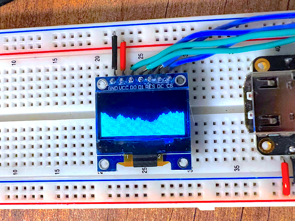
As an example project let's use our screen module we built in this series (here) and let's create a graph showing a running total of random numbers.
To do this is pretty simple, we can start with some value and every X amount of time take a new random number adding it to our running total. Our screen has 128 pixel columns, so if we want to display each value as 1 column of pixels then we will need to store 128 different graph values.
With a value stored for each column, we simply have to decide which pixels in the column should be lit up based on the columns specific stored value.
Some Boilerplate
So in our project we should have screen.v and lfsr.v (and the test file lfsr_tb.v). The next step is to create our Makefile:
BOARD=tangnano9k
FAMILY=GW1N-9C
DEVICE=GW1NR-LV9QN88PC6/I5

all: lfsr.fs

# Synthesis
lfsr.json: top.v screen.v lfsr.v
	yosys -p "read_verilog screen.v lfsr.v top.v; synth_gowin -noalu -top top -json lfsr.json"

# Place and Route
lfsr_pnr.json: lfsr.json
	nextpnr-gowin --json lfsr.json --write lfsr_pnr.json --enable-auto-longwires --enable-globals --freq 27 --device ${DEVICE} --family ${FAMILY} --cst ${BOARD}.cst

# Generate Bitstream
lfsr.fs: lfsr_pnr.json
	gowin_pack -d ${FAMILY} -o lfsr.fs lfsr_pnr.json

# Program Board
load: lfsr.fs
	openFPGALoader -b ${BOARD} lfsr.fs -f

# Generate Simulation
lfsr_test.o: lfsr.v lfsr_tb.v
	iverilog -o lfsr_test.o -s test lfsr.v lfsr_tb.v

# Run Simulation
test: lfsr_test.o
	vvp lfsr_test.o

# Cleanup build artifacts
clean:
	rm lfsr.fs lfsr_test.o

.PHONY: load clean test
.INTERMEDIATE: lfsr_pnr.json lfsr.json lfsr_test.o
This is our standard boilerplate makefile with 3 main commands make to run the toolchain to run synthesis, place & route and generate the bitstream. You have make load (or sudo make load) to program the FPGA and make test will run the test-bench we created and generate the VCD file for debugging.
We also need a constraints file, so create a file called tangnano9k.cst with the following:
IO_LOC "clk" 52;
IO_PORT "clk" PULL_MODE=UP;

IO_LOC "ioCs" 36;
IO_PORT "ioCs" IO_TYPE=LVCMOS33 PULL_MODE=DOWN DRIVE=8;
IO_LOC "ioDc" 39;
IO_PORT "ioDc" IO_TYPE=LVCMOS33 PULL_MODE=DOWN DRIVE=8;
IO_LOC "ioReset" 25;
IO_PORT "ioReset" IO_TYPE=LVCMOS33 PULL_MODE=DOWN DRIVE=8;
IO_LOC "ioSdin" 26;
IO_PORT "ioSdin" IO_TYPE=LVCMOS33 PULL_MODE=DOWN DRIVE=8;
IO_LOC "ioSclk" 27;
IO_PORT "ioSclk" IO_TYPE=LVCMOS33 PULL_MODE=DOWN DRIVE=8;
These are the required pins to drive the screen and the clock signal from the on-board 27MHZ crystal.
The last file we need to make is top.v.
Implementing the Grapher
To get started let's create top.v adding all the inputs and outputs from the constraints file:
`default_nettype none

module top
#(
  parameter STARTUP_WAIT = 32'd10000000
)
(
    input clk,
    output ioSclk,
    output ioSdin,
    output ioCs,
    output ioDc,
    output ioReset
);
    wire [9:0] pixelAddress;
    reg [7:0] pixelData = 0;

    screen #(STARTUP_WAIT) scr(
        clk,
        ioSclk,
        ioSdin,
        ioCs,
        ioDc,
        ioReset,
        pixelAddress,
        pixelData
    );


endmodule
We also hooked up our screen module. Next let's create a 32-bit LFSR which we will use to generate our random numbers:
wire randomBit;

lfsr #(
    .SEED(32'd1),
    .TAPS(32'h80000412),
    .NUM_BITS(32)
) l1(
    clk,
    randomBit
);

reg [3:0] tempBuffer = 0;
always @(posedge clk) begin
    tempBuffer <= {tempBuffer[2:0], randomBit};
end
We create a wire to output the random bit from the LFSR and then create a new LFSR instance setting the parameters to be a 32-bit LFSR with a valid taps for such a size.
We then create a 4-bit buffer to hold our 4-bit random number which we will use to update our running total.
The always block will shift in the random bit on every clock pulse, pushing all the other bits up.
Next up we need some registers for storing our graph data. Like mentioned above, we will want to store 128 graph values (data points) one for each column. If we say that each number is an 8-bit number, then we will need 8 * 128 bits.
localparam NUM_BITS_STORAGE = 8 * 128;
reg [NUM_BITS_STORAGE - 1:0] graphStorage = 0;

reg [7:0] graphValue = 127;
reg [6:0] graphColumnIndex = 0;
reg [19:0] delayCounter = 0;
So we have a local parameter holding the number of bits, and then a new register to hold all 128 bytes.
Next we have a register to hold the current running total, we initialize it to 127, so it will start out in the middle of the graph. The next register graphColumnIndex stores which byte in graphStorage we currently need to write to and finally delayCounter will count clock cycles to delay taking a new random number.
If we would update the graph at full speed it would be too fast and would look just like random noise. To make it look like a real-time graph we need to slow it down, so we will wait 900,000 clock cycles between saving a new datapoint to our graph giving us about 30 FPS (27MHZ / 900,000 = 30).
Now let's take a look at the actual code that will do this:
always @(posedge clk) begin
    if (delayCounter == 20'd900000) begin
        if (tempBuffer != 4'd15)
            graphValue <= graphValue + tempBuffer - 8'd7;
        delayCounter <= 0;
        graphStorage[({3'd0, graphColumnIndex} << 3)+:8] <= graphValue;
        graphColumnIndex <= graphColumnIndex + 1;
    end
    else
        delayCounter <= delayCounter + 1;
end
If our delayCounter reached 900,000 then we update the current graphValue (for next time) and we store the last value into graphStorage. We don't want our graph to only go up, so we subtract 7 from the number to change our 4-bit number from being 0-15 to be -7 to 8. The problem with this is that we have more positive numbers then negative so to get around this, we don't update the running total when the tempBuffer was 15 to essentially treat 8 (15-7) as another zero. This makes the positive and negative numbers balanced making our graph less likely to go out of bounds.
Besides for that I think it is worth explaining this notation:
graphStorage[({3'd0, graphColumnIndex} << 3)+:8]Basically graphColumnIndex stores the byte index and the [] operator takes a bit index. So we need to multiply by 8, this can be achieved by shifting left 3 times as each shift multiplies by 2. The problem is graphColumnIndex doesn't have room to shift, if not handled this would cause the top 3 bits to be truncated not allowing us to reach all bit indices. To fix this we first prepend three zeroes to make room for the shifting and then shift.
The +:8 just means take the index to the left of the plus sign, and add eight bits which is like a relative index instead of redoing the calculation to give an absolute index value.
With that we now have storage which updates 30 times a second and has 128 total columns of random bytes. The last step is to just draw them to the screen.
Drawing the Columns
The way our screen works is it will set a specific pixel byte address inside pixelAddress for a byte representing 8 pixels on screen. We have about 20 clock cycles to calculate what needs to be displayed and put the value inside of pixelData.
Let's start out by splitting up the requested pixelAddress into an X and Y coordinate on screen:
wire [6:0] xCoord;
wire [2:0] yCoord;

assign xCoord = pixelAddress[6:0] + graphColumnIndex;
assign yCoord = 3'd7-pixelAddress[9:7];
We have 128 columns which means we need 7-bits for the X direction and we have 8 rows requiring 3-bits. Each of the addresses represents 8-vertical pixels giving us a total of 64 pixels in height. So the X coordinate is pretty simple, it is simply the first 7 bits from pixelAddress. We add to this graphColumnIndex to offset the screen position to create a scrolling effect every time we store a new value in the graph storage we increment the graphColumnIndex value so by adding it here we shift the X-axis by the same amount making each column display the value that was in the next column essentially scrolling the graph backwards by one.
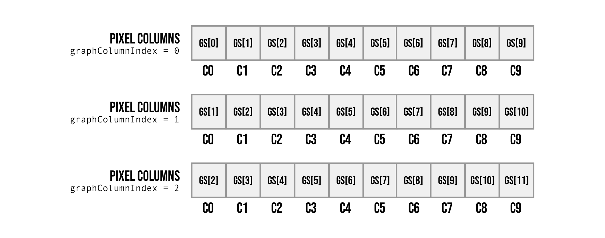
This is an example of the first 10 columns when graphColumnIndex equals 0,1 and 2. You can see the what was displayed in column 1 (C1) gets shifted to column 0 (C0) when graphColumnIndex is incremented, scrolling the graph left. This works because we have exactly a power of 2 columns (128), so even if we go over 128 by adding graphColumnIndex it will just overflow and loop back to the beginning. If we had a number of columns that wasn't a power of 2, for example 30, we would have to manually handle the wrapping by performing a modulo operation dividing by 30 and taking the remainder.
For the Y coordinate, theoretically we only need the last 3-bits of pixel address. The screen coordinate system places (0,0) at the top left and (127,7) at the bottom right. We want to flip the Y coordinate so that 0 is at the bottom and 7 is at the top, to do this we simply start with 7 and subtract the screen's Y coordinate flipping the axis.
Next we need to get the current value to display from graphStorage based on the current address:
wire [7:0] currentGraphValue;
wire [5:0] maxYHeight;

assign currentGraphValue = graphStorage[({3'd0,xCoord} << 3)+:8];
assign maxYHeight = currentGraphValue[7:2];
The first 8-bit wire will hold the current value to display from the graph storage. Each time we will be filling out a byte for a single column of pixels and each byte in graphStorage is for a single column making it so we only need to retrieve 1 byte to calculate how to render the graph. We can simply multiply the xCoord by 8 (by shifting 3 to the left) giving us the exact starting bit address and retrieve the relevant byte from graphStorage connecting it to currentGraphValue.
The next wire maxYHeight is just to convert it to the screen's dimensions, currentGraphValue can be a number from 0-255 yet our screen only has 64 pixels in height so we divide by 4 via removing the last two bytes (like shifting right by 2).
The final step is to calculate which pixels in the current byte we want to draw. maxYHeight has already been mapped to pixels by dividing it by 4, so let's say currently the value of maxYHeight is 25 that would mean we want the bottom 25 pixels in the column to be lit up and the rest not.
always @(posedge clk) begin
    pixelData[0] <= ({yCoord,3'd7} < maxYHeight);
    pixelData[1] <= ({yCoord,3'd6} < maxYHeight);
    pixelData[2] <= ({yCoord,3'd5} < maxYHeight);
    pixelData[3] <= ({yCoord,3'd4} < maxYHeight);
    pixelData[4] <= ({yCoord,3'd3} < maxYHeight);
    pixelData[5] <= ({yCoord,3'd2} < maxYHeight);
    pixelData[6] <= ({yCoord,3'd1} < maxYHeight);
    pixelData[7] <= ({yCoord,3'd0} < maxYHeight);
end
On each clock cycle we set each of the 8 pixel bits to be 1 if the pixel Y index is less than the max height we calculated from graph storage. The value in yCoord is the byte index so to get a bit index we multiply by 8 and then each pixel index get's a different suffix from 0-7.
So for example if yCoord equals 1, that means that we are now dealing with pixels row indexed 8-15 by shifting 3 and adding the number 0-7 we get all these indices. For each pixel index we simply need to compare it to maxYHeight and if it is lower than or equals then it will return 1 lighting the specific pixel up.
The reason the numbers are reversed, like in pixelData[0] we put yCoord + 7 and not yCoord + 0 is because we flipped the Y axis so it is reversed.
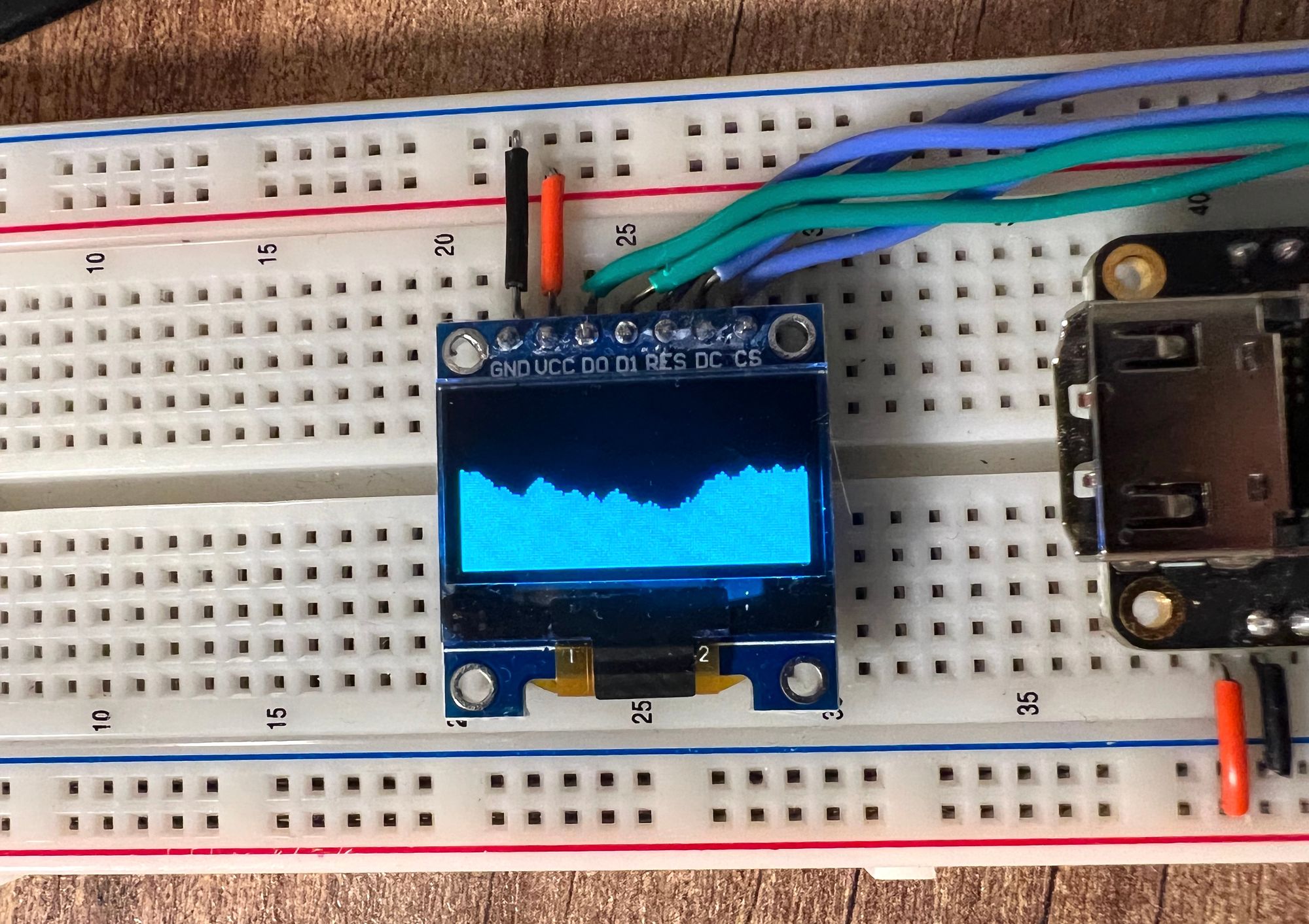
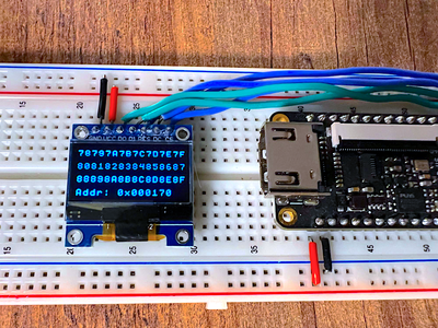
With that the project should be done, running it now with make load should give us something like the following:
Conclusion
In this part we took a look at generating pseudo-random numbers using LFSRs and built a scrolling graph to show us the random number affecting a running total over time.
Going through LFSRs I hope it was clear that it might not be the best match for security systems as there is a correlation between numbers, but for most user-based applications where you just need a bit of "randomness" it is very cheap to implement both in design and in the number of resources required to provide pretty good results.
Like always all the code can be found on github here.
If you have any questions or comments please feel free to leave them down below in the comment section or on twitter @LushayLabs.
All parts used in the series can be found on our store here.
Thank you for reading

