
In this article we will go through different methods of converting data for display and we will be combining all the modules we created up until now in-order to wrap up our OLED mini project.
The Goal
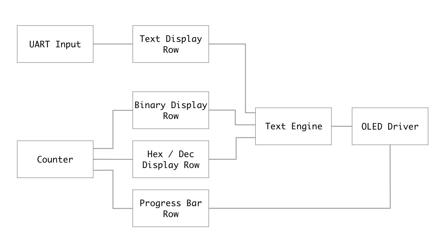
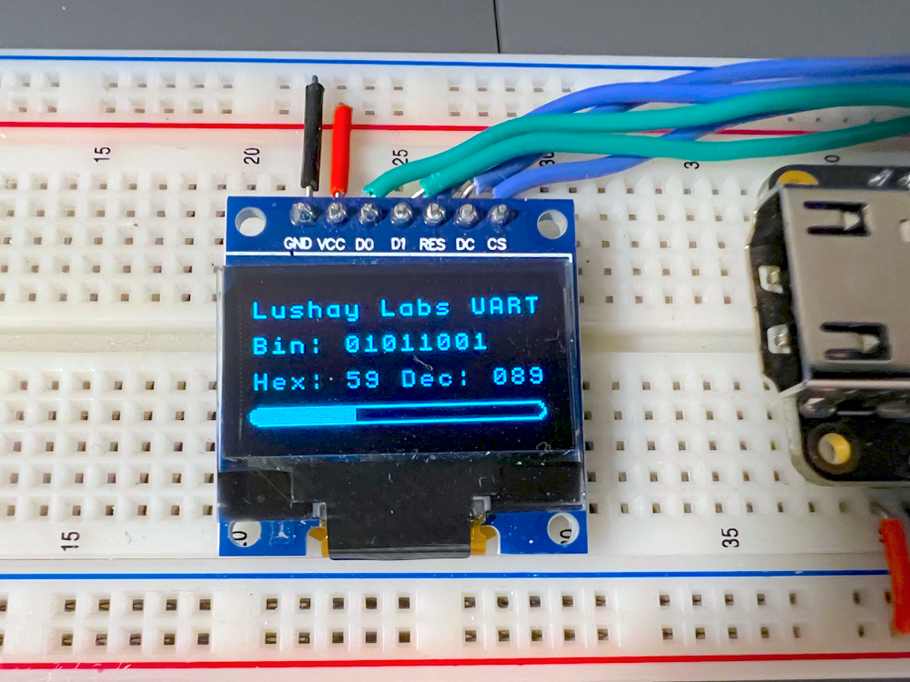
We will be building a project that splits the screen into 4 rows like in the previous article, but here each row will have a different data representation / conversion and will show how we can update multiple areas of the screen in parallel using our design.
The first row of the screen will display ASCII text, much like we did last time, except now we will connect it to our UART module we built here to make the text dynamic. So as you type on the computer the text will be displayed on the first row.
Since both the data coming in over UART and the data going out to our text engine are both ASCII format, no conversion is required here.
Next we will have an 8-bit counter which will count once a second which we are using to give us a binary number. We are using a counter to keep it simple but this could be a sensor value or calculation result and besides for changing the counter module all the rest of the design would stay the same.
The next two lines of the screen will be used to display the number both in binary, hex and in decimal format. So in the case of the binary row we have to convert the 8-bit number into 8 ascii bytes each of which can be a '1' or '0' (49/48 ascii code). For hex and decimal we need to convert the number to it's representation in base 16 / base 10 respectively and convert the result into ASCII characters.
The final row will not use our text engine and will show how we can combine both graphics and text on screen. This last row will be a simple progress bar where when our counter is 0 the progress bar would be empty and for 255 it would be full.
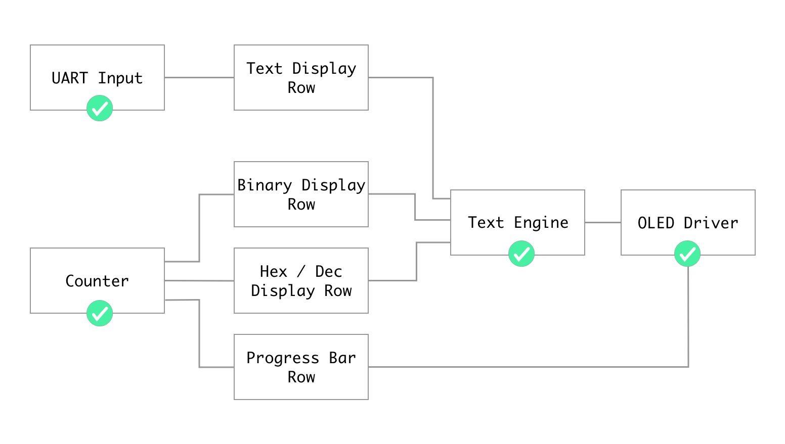
From the previous articles we have gone through the checked components, and even went over the "Text Display" row although without it being editable, so in this article we will be completing the components for the four display rows.
Preparing The Project
There are a few changes that we need to make to the UART and Text Engine components to use them in this project. For the UART we can delete all the transmitter stuff and expose the data and byteReady flag via output parameters:
`default_nettype none

module uart
#(
    parameter DELAY_FRAMES = 234 // 27,000,000 (27Mhz) / 115200 Baud rate
)
(
    input clk,
    input uartRx,
    output reg byteReady,
    output reg [7:0] dataIn
);

localparam HALF_DELAY_WAIT = (DELAY_FRAMES / 2);

reg [3:0] rxState = 0;
reg [12:0] rxCounter = 0;
reg [2:0] rxBitNumber = 0;

localparam RX_STATE_IDLE = 0;
localparam RX_STATE_START_BIT = 1;
localparam RX_STATE_READ_WAIT = 2;
localparam RX_STATE_READ = 3;
localparam RX_STATE_STOP_BIT = 5;

always @(posedge clk) begin
    case (rxState)
        RX_STATE_IDLE: begin
            if (uartRx == 0) begin
                rxState <= RX_STATE_START_BIT;
                rxCounter <= 1;
                rxBitNumber <= 0;
                byteReady <= 0;
            end
        end
        RX_STATE_START_BIT: begin
            if (rxCounter == HALF_DELAY_WAIT) begin
                rxState <= RX_STATE_READ_WAIT;
                rxCounter <= 1;
            end else
                rxCounter <= rxCounter + 1;
        end
        RX_STATE_READ_WAIT: begin
            rxCounter <= rxCounter + 1;
            if ((rxCounter + 1) == DELAY_FRAMES) begin
                rxState <= RX_STATE_READ;
            end
        end
        RX_STATE_READ: begin
            rxCounter <= 1;
            dataIn <= {uartRx, dataIn[7:1]};
            rxBitNumber <= rxBitNumber + 1;
            if (rxBitNumber == 3'b111)
                rxState <= RX_STATE_STOP_BIT;
            else
                rxState <= RX_STATE_READ_WAIT;
        end
        RX_STATE_STOP_BIT: begin
            rxCounter <= rxCounter + 1;
            if ((rxCounter + 1) == DELAY_FRAMES) begin
                rxState <= RX_STATE_IDLE;
                rxCounter <= 0;
                byteReady <= 1;
            end
        end
    endcase
end
endmoduleFor a full explanation on this module you can look at the article where we created it here. For the text engine component we want to also expose the character address and chosen character, so that we can control them from the top module. The text engine should look like the following after those changes:
`default_nettype none

module textEngine (
    input clk,
    input [9:0] pixelAddress,
    output [7:0] pixelData,
    output [5:0] charAddress,
    input [7:0] charOutput
);
    reg [7:0] fontBuffer [1519:0];
    initial $readmemh("font.hex", fontBuffer);

    wire [2:0] columnAddress;
    wire topRow;

    reg [7:0] outputBuffer;
    wire [7:0] chosenChar;

    always @(posedge clk) begin
        outputBuffer <= fontBuffer[((chosenChar-8'd32) << 4) + (columnAddress << 1) + (topRow ? 0 : 1)];
    end

    assign charAddress = {pixelAddress[9:8],pixelAddress[6:3]};
    assign columnAddress = pixelAddress[2:0];
    assign topRow = !pixelAddress[7];

    assign chosenChar = (charOutput >= 32 && charOutput <= 126) ? charOutput : 32;
    assign pixelData = outputBuffer;
endmoduleIt receives an ASCII character via charOutput and converts it into pixelData depending on the column / topRow etc. The article where we built this module can be found here.
Next if you are using the OSS toolchain manually you can setup your makefile (if using the Lushay Code plugin this can be skipped)
BOARD=tangnano9k
FAMILY=GW1N-9C
DEVICE=GW1NR-LV9QN88PC6/I5

all: data.fs

# Synthesis
data.json: top.v text.v screen.v uart.v rows.v
	yosys -p "read_verilog screen.v uart.v rows.v text.v top.v; synth_gowin -noalu -top top -json data.json"

# Place and Route
data_pnr.json: data.json
	nextpnr-gowin --json data.json --write data_pnr.json --enable-globals --freq 27 --enable-auto-longwires --device ${DEVICE} --family ${FAMILY} --cst ${BOARD}.cst

# Generate Bitstream
data.fs: data_pnr.json
	gowin_pack -d ${FAMILY} -o data.fs data_pnr.json

# Program Board
load: data.fs
	openFPGALoader -b ${BOARD} data.fs -f

# Generate Simulation
data_test.o: text.v data_tb.v top.v uart.v rows.v screen.v
	iverilog -o data_test.o -s test text.v uart.v rows.v data_tb.v top.v screen.v

# Run Simulation
test: data_test.o
	vvp data_test.o

# Generate Font
font: font.hex
font.hex:
	node ./scripts/generate_font.js

# Cleanup build artifacts
clean:
	rm data.vcd data.fs data_test.o

.PHONY: load clean test
.INTERMEDIATE: data_pnr.json data.json data_test.o
The main difference is that here I added another file called rows.v where we will put the modules for our 4 screen rows and also made sure to set the frequency in nextpnr. We can update our top module in top.v:
module top
#(
  parameter STARTUP_WAIT = 32'd10000000
)
(
    input clk,
    output ioSclk,
    output ioSdin,
    output ioCs,
    output ioDc,
    output ioReset,
    input uartRx
);
    wire [9:0] pixelAddress;
    wire [7:0] textPixelData, chosenPixelData;
    wire [5:0] charAddress;
    reg [7:0] charOutput;

    wire uartByteReady;
    wire [7:0] uartDataIn;
    wire [1:0] rowNumber;

    screen #(STARTUP_WAIT) scr(
        clk,
        ioSclk,
        ioSdin,
        ioCs,
        ioDc,
        ioReset,
        pixelAddress,
        chosenPixelData
    );

    textEngine te(
        clk,
        pixelAddress,
        textPixelData,
        charAddress,
        charOutput
    );

    assign rowNumber = charAddress[5:4];

    uart u(
        clk,
        uartRx,
        uartByteReady,
        uartDataIn
    );

    always @(posedge clk) begin
        case (rowNumber)
            0: charOutput <= "A";
            1: charOutput <= "B";
            2: charOutput <= "C";
            3: charOutput <= "D";
        endcase
    end
    assign chosenPixelData = textPixelData;
endmodule
We start by creating instances of our screen driver, text engine and uart modules, connecting them up with all the required registers, nothing new here. The last always block will choose a character for now according to the rowNumber. So the whole first row should be "A" and the second "B" and so on, this is instead of the textRow component from the previous article.
Finally our constraints file now needs to include the uart rx pin:
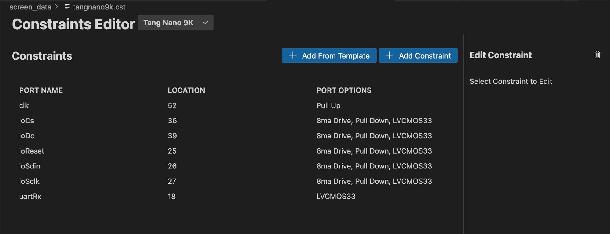
Or manually like this:
IO_LOC "clk" 52;
IO_PORT "clk" PULL_MODE=UP;

IO_LOC "ioCs" 36;
IO_PORT "ioCs" IO_TYPE=LVCMOS33 PULL_MODE=DOWN DRIVE=8;
IO_LOC "ioDc" 39;
IO_PORT "ioDc" IO_TYPE=LVCMOS33 PULL_MODE=DOWN DRIVE=8;
IO_LOC "ioReset" 25;
IO_PORT "ioReset" IO_TYPE=LVCMOS33 PULL_MODE=DOWN DRIVE=8;
IO_LOC "ioSdin" 26;
IO_PORT "ioSdin" IO_TYPE=LVCMOS33 PULL_MODE=DOWN DRIVE=8;
IO_LOC "ioSclk" 27;
IO_PORT "ioSclk" IO_TYPE=LVCMOS33 PULL_MODE=DOWN DRIVE=8;

IO_LOC "uartRx" 18;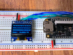
IO_PORT "uartRx" IO_TYPE=LVCMOS33;Create a new file rows.v and run the project by clicking on "FPGA Toolchain" and then "Build and Program" (or make load if not using our plugin). Running the project now should give you something like the following:
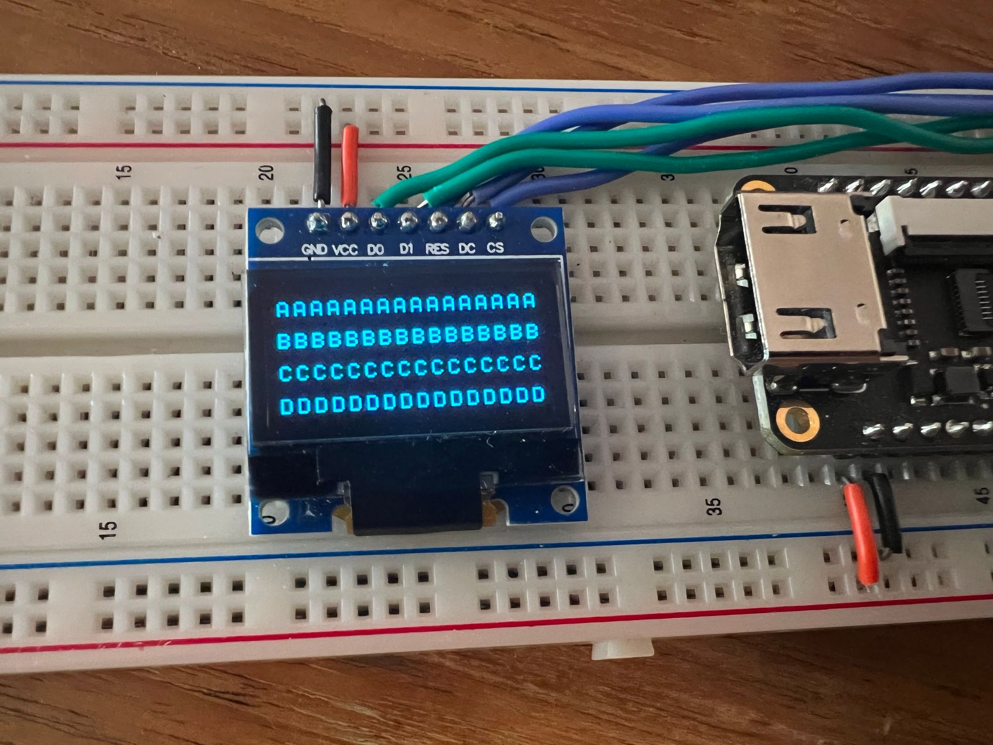
It is still pretty much like before with just static text, but now we re-organized the project and imported all our modules so we can get into implementing the dynamic data rows.
The UART Row
The first row we are going to implement is the UART row. This row will take each character coming in from the UART module and add it to a register. We will store up to 16 characters as each row in our text engine can fit 16 characters. Inside the rows.v file let's add a new module with the following:
module uartTextRow (
    input clk,
    input byteReady,
    input [7:0] data,
    input [3:0] outputCharIndex,
    output [7:0] outByte
);
    localparam bufferWidth = 128;
    reg [(bufferWidth-1):0] textBuffer = 0;
    reg [3:0] inputCharIndex = 0;
    reg [1:0] state = 0;

    localparam WAIT_FOR_NEXT_CHAR_STATE = 0;
    localparam WAIT_FOR_TRANSFER_FINISH = 1;
    localparam SAVING_CHARACTER_STATE = 2;

    always @(posedge clk) begin
        case (state)
     	    // state machine here
        endcase
    end

    assign outByte = textBuffer[({4'd0, outputCharIndex} << 3)+:8];
endmodule
We receive as inputs the clock, whether or not the UART has a ready byte (byteReady) that it read, that UART data which is the character itself and the current character we want read outputCharIndex. We also have one output which is supposed to be the character we want to display in ASCII format.
Inside the module we create a buffer to store our 16 characters (each 8 bit) and we create a register to store the input character index. This register stores the column where we should put the next character that comes in.
If you think a serial console, or displaying text in general. The first character goes in index zero then the next character goes to its right at index 1, etc. so the current index will be stored in inputCharIndex.
Next we have a register to hold the current state as this module has multiple states. The reason for the multiple states is to sort of debounce the UART module. If we remember the UART module will set byteReady high once it finishes receiving a character. But it never clears this flag until the next character comes in. So if we were to add a character on every clock pulse where byteReady is high we would be adding the same character multiple times.
We can instead wait first for the byteReady flag to be set low which indicates a new character is being received, then in another state wait for byteReady to go back high, as we can't read the character until it is complete, and finally in the last state we can be sure that we have a character ready and that it is a new character that we haven't dealt with yet.
Since the data coming in is already ASCII data we don't need to convert anything and we assign outByte to be the character from our character register at the current index * 8 (or shifted 3 times) as each character is 8 bits.
The actual states look like the following:
WAIT_FOR_NEXT_CHAR_STATE: begin
    if (byteReady == 0)
        state <= WAIT_FOR_TRANSFER_FINISH;
end
WAIT_FOR_TRANSFER_FINISH: begin
    if (byteReady == 1)
        state <= SAVING_CHARACTER_STATE;
end
SAVING_CHARACTER_STATE: begin
    inputCharIndex <= inputCharIndex + 1;
    textBuffer[({4'd0,inputCharIndex}<<3)+:8] <= data;
    state <= WAIT_FOR_NEXT_CHAR_STATE;
end
Like mentioned, first we wait for byteReady to go low, then high and then we add the character to our textBuffer and increment the index. We can even change the SAVING_CHARACTER_STATE to allow for backspace with minimal changes:
SAVING_CHARACTER_STATE: begin
    if (data == 8'd8 || data == 8'd127) begin
        inputCharIndex <= inputCharIndex - 1;
        textBuffer[({4'd0,inputCharIndex-4'd1}<<3)+:8] <= 8'd32;
    end
    else begin
        inputCharIndex <= inputCharIndex + 1;
        textBuffer[({4'd0,inputCharIndex}<<3)+:8] <= data;
    end
    state <= WAIT_FOR_NEXT_CHAR_STATE;
end
In this version we check if the character from UART (data) equals the backspace or delete keys (8 or 127 in ascii) in which case we decrement the character index and replace the previous character with a space (32 in ascii). Otherwise like before we increment the character index and store the character as-is.
In our top module in top.v we can instantiate and hookup our UART text row:
wire [7:0] charOut1;

uartTextRow row1(
    clk,
    uartByteReady,
    uartDataIn,
    charAddress[3:0],
    charOut1
);
And then we can update our always block to include the output from our new module:
always @(posedge clk) begin
case (rowNumber)
0: charOutput <= charOut1;
1: charOutput <= "B";
2: charOutput <= "C";
3: charOutput <= "D";
endcase
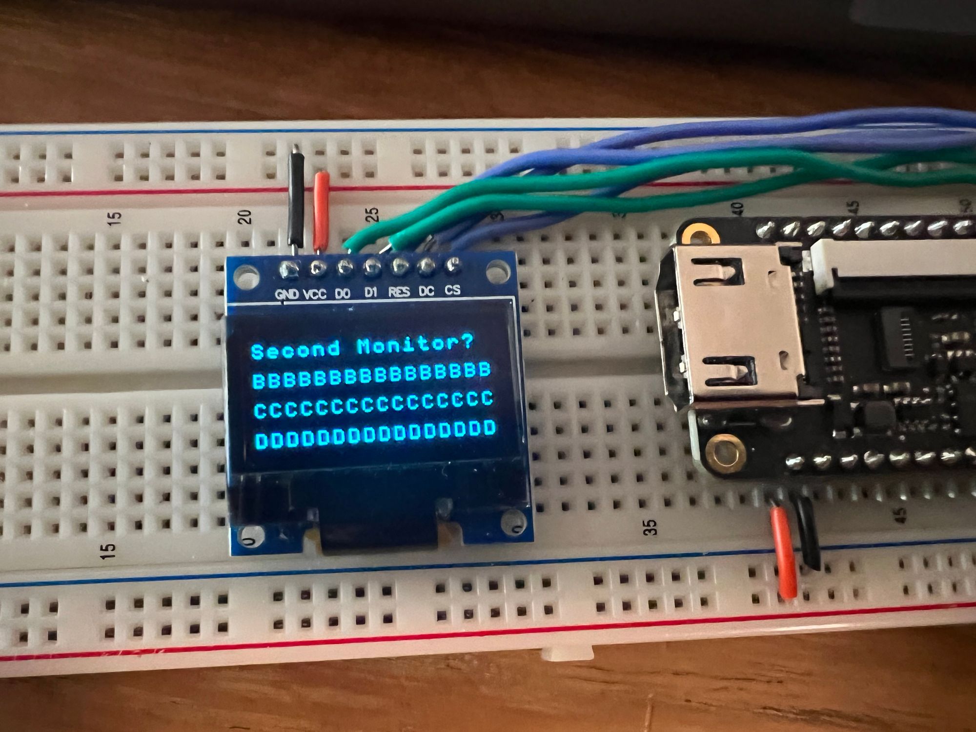
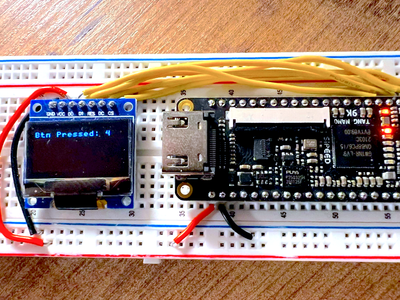
endRunning our project now, you should be able to connect over serial terminal and anything typed should be displayed and look like the following:
The Binary Row
Our next row is another easy one, when displaying bits you only have two options to display a "1" or a "0". To display data in binary format you need 1 character for each bit and then depending on if the bit is a 1 or 0 you choose the appropriate character.
In the rows.v file we can add the following:
module binaryRow(
    input clk,
    input [7:0] value,
    input [3:0] outputCharIndex,
    output [7:0] outByte
);
    reg [7:0] outByteReg;
    wire [2:0] bitNumber;

    assign bitNumber = outputCharIndex - 5;

    always @(posedge clk) begin
        case (outputCharIndex)
            0: outByteReg <= "B";
            1: outByteReg <= "i";
            2: outByteReg <= "n";
            3: outByteReg <= ":";
            4: outByteReg <= " ";
            13, 14, 15: outByteReg <= " ";
            default: outByteReg <= (value[7-bitNumber]) ? "1" : "0";
        endcase
    end

    assign outByte = outByteReg;
endmodule
In our case we will be displaying an 8 bit value, so we receive as input parameters the clock, the value to display and which of the 16 characters for this row is currently being requested. For output parameters we have a single parameter which is the ASCII character we want to display.
We create a register to store our output character which we assign to outByte at the end of the module. The 3-bit wire called bit number is just because I want to write "Bin: " to the screen which is 5 characters, so when we are on character index 5 I want it to represent bit number 0.
Inside the always block we have a switch case statement where for the first 5 indices we output the appropriate character for each index to spell out "Bin: ". For the last 3 indices we want to leave blank as we only need 13 characters (5 for text+8 bits) out of the 16 characters.
For the 8 bits where we are displaying the binary data we check the current bit if it is high we output a "1" in ascii and if not a "0". Its worth noting we flip the direction (by doing 7-index) since when writing binary numbers it is common that the least significant bit is on the right hand side (like in base 10).
To test this out we need to have a value to display, so let's add to top.v a simple counter module based on our previous counter from the first article in this series.
module counterM(
    input clk,
    output reg [7:0] counterValue = 0,
);
    reg [32:0] clockCounter = 0;

    localparam WAIT_TIME = 27000000;

    always @(posedge clk) begin
        if (clockCounter == WAIT_TIME) begin
            clockCounter <= 0;
            counterValue <= counterValue + 1;
        end
        else
            clockCounter <= clockCounter + 1;
    end
endmodule
We receive the clock as input an output an 8-bit counter which updates once a second. Notice the keyword reg on the output parameter, that will automatically create an output register and assign it to the output wire.
To accomplish a 1Hz counter, we create a secondary counter which will count 27,000,000 ticks which at the 27Mhz of the tang nano will result in an update on the output counter once a second.
We can now add the following to the top module:
wire [7:0] counterValue;
wire [7:0] charOut2;

counterM c(clk, counterValue);

binaryRow row2(
    clk,
    counterValue,
    charAddress[3:0],
    charOut2
);
And then we can update our always block to take charOut2 for the second row:
always @(posedge clk) begin
case (rowNumber)
0: charOutput <= charOut1;
1: charOutput <= charOut2;
2: charOutput <= "C";
3: charOutput <= "D";
endcase
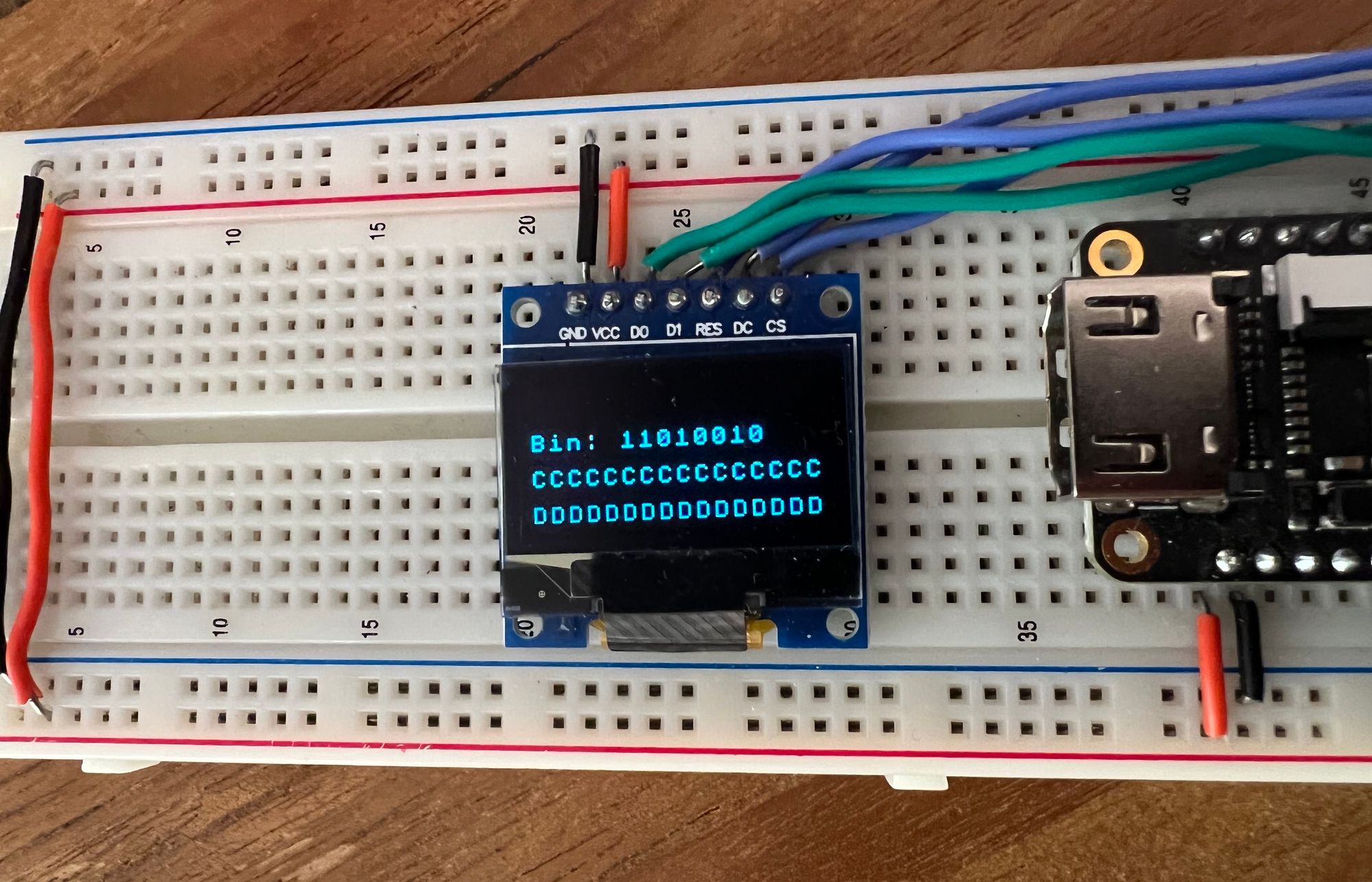
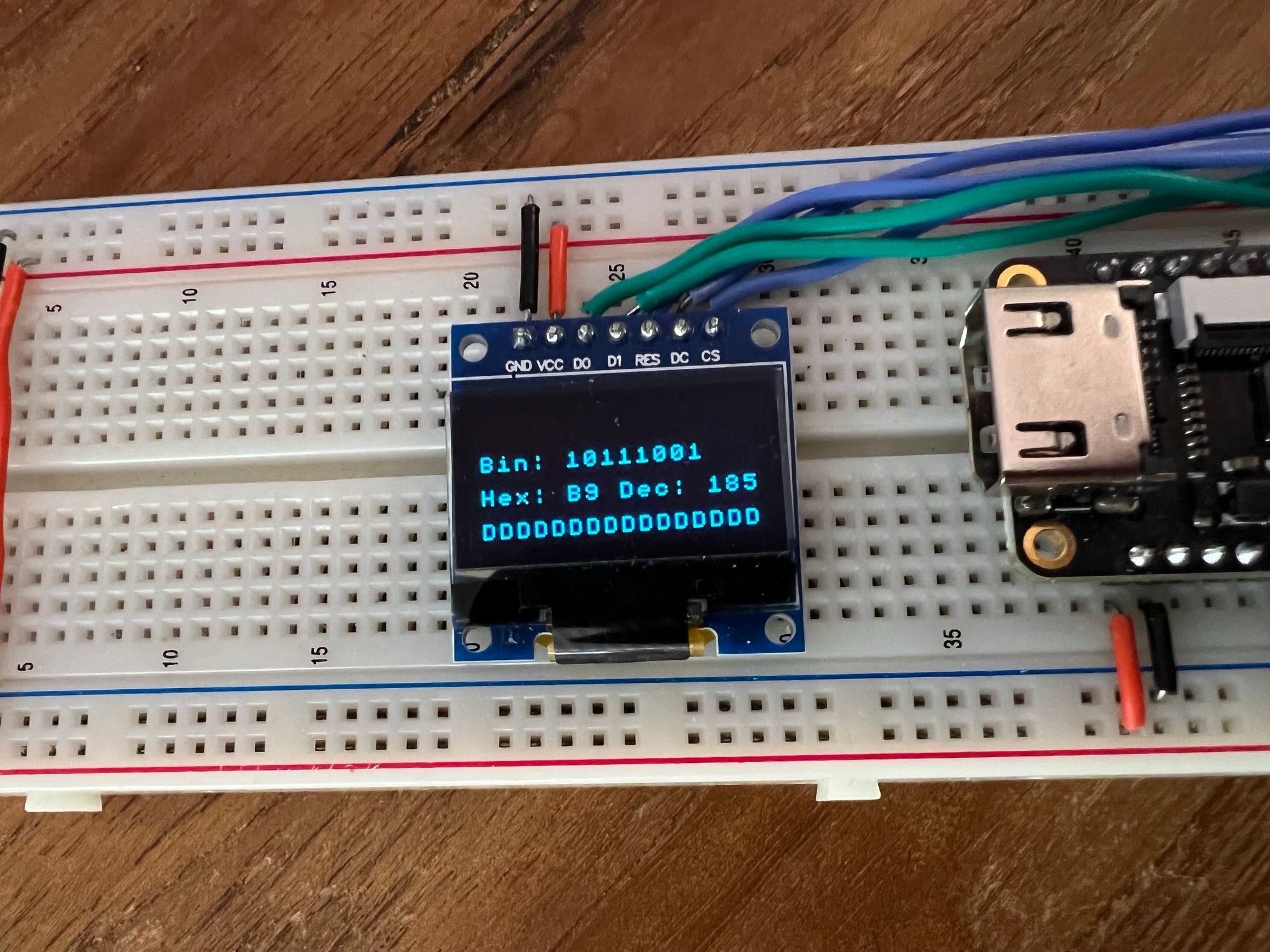
endRunning this now should give us the following:
The Hex / Decimal Row
The next screen row module we want to implement is the row which will display the same counter value in hex and decimal representation.
Hex is almost as easy as binary, since hex is base 16 which is also a power of 2 like binary, it means that every four bits translate to exactly one hex character. So to display our 8-bit number we need exactly 2 hex characters. The conversion for each hex character is also pretty simple, with 4-bits we can have a maximum value of 15, for 0-9 we simply put that same digit as the output in ascii, and from 10-15 we move to letters A-F.
module toHex(
    input clk,
    input [3:0] value,
    output reg [7:0] hexChar = "0"
);
    always @(posedge clk) begin
        hexChar <= (value <= 9) ? 8'd48 + value : 8'd55 + value;
    end
endmodule
In this helper module we receive the 4-bit number which we need to convert to an ASCII letter. Like we said if the value is less than 10, we simply add the offset to the "0" ascii character since all the numbers are in order in the ASCII table. So a value of zero will give ascii code 48 which is "0", for value 1 it will be ascii code 49 which is "1", etc..
Once we reach 10, the values for A-F do not come right after the numbers in the ASCII table so here we need to jump to ascii code 65 to represent "A". Since value already equals 10 we subtract 10 from 65 (the ascii code for "A") and we get an offset of 55.
We can now create our hex / dec row:
module hexDecRow(
    input clk,
    input [7:0] value,
    input [3:0] outputCharIndex,
    output [7:0] outByte
);
    reg [7:0] outByteReg;

    wire [3:0] hexLower, hexHigher;
    wire [7:0] lowerHexChar, higherHexChar;

    assign hexLower = value[3:0];
    assign hexHigher = value[7:4];

    toHex h1(clk, hexLower, lowerHexChar);
    toHex h2(clk, hexHigher, higherHexChar);

    always @(posedge clk) begin
        case (outputCharIndex)
            0: outByteReg <= "H";
            1: outByteReg <= "e";
            2: outByteReg <= "x";
            3: outByteReg <= ":";
            5: outByteReg <= higherHexChar;
            6: outByteReg <= lowerHexChar;
            default: outByteReg <= " ";
        endcase
    end

    assign outByte = outByteReg;
endmodule
Very similar to the binary row. We receive the counter value and need to output an ASCII character based on the current character index.
We start by creating wires to split the 8-bit byte into two 4-bit sections and then we use the toHex module we just created in-order to convert those 4 bytes into an ASCII character.
Inside the always block we are again outputting the character according to the requested character index. This was slightly harder than the binary row since we have more than 2 options for the output character, but because of the common power with base 2 and the layout of the ASCII table it is a relatively straight forward conversion.
Base 10 on the other hand, or decimal format does not share a common power with binary, so we can't simply split up the original byte into individual characters. We need an algorithm or method to convert between the two formats.
Converting Binary to Decimal
There are multiple ways to do this conversion, but in this article we will be implementing an algorithm called "Double Dabble". The principle of the algorithm is to use the same hex conversion we did above by making our base-10 system function like base-16.
This is possible because if you think about it, 0-9 in both systems work exactly the same, the problem is that base-10 needs to reset after 9 back to 0 and add another digit (10) whereas base-16 will continue until passing 15 to do this.
If we designate 4-bits for each digit and shifted in the binary value into the bits we created for the digits we would in-deed have each digit separated in base 16. Another thing to note is that by shifting bits in we are essentially multiplying by 2 each time. So the trick is every time a base 10 number would move to the next digit (would be above 10) we add 6 to make the base16 digit also roll over and behave like the base 10 equivalent.
So by adding 6 we convert:
10 -> 16 which in base 16 is 10
11 -> 17 which in base 16 us 11
and so on, as you can see for numbers 10 and up, by adding six we convert it to the hex number with the same digits.
In practice since each shift is multiplying by 2, then we can perform the addition before the shifting in which case we want to add 3 every time the value for a digit is equal to or greater than 5 (instead of adding 6 for values >= 10).
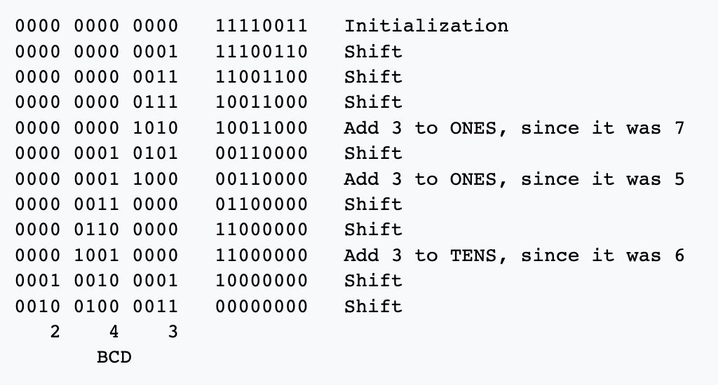
This is an example from wikipedia where we are converting 243 from binary to individual digits (BCD). The maximum value for an 8-bit value is 255 so we need three digits, and we are using 4 bits per digit because we are simulating base-16.
Since our number is 8-bits we need to shift 8 times to get the full number into our digits register. At each of these 8 iterations we first check if any of the digits are over 5, if so we know that after the next shift they will be over 10 and need to overflow so we add 3 to that sub digit, which will cause the hex digit to overflow after the shift.
After adding any offsets required we shift the next bit in, and perform this for the number of bits in the original number. Once completed each 4-bit section will have the value for 1 of the 3 decimal digits. To implement this we can create a module as follows:
module toDec(
    input clk,
    input [7:0] value,
    output reg [7:0] hundreds = "0",
    output reg [7:0] tens = "0",
    output reg [7:0] units = "0"
);
    reg [11:0] digits = 0;
    reg [7:0] cachedValue = 0;
    reg [3:0] stepCounter = 0;
    reg [3:0] state = 0;

    localparam START_STATE = 0;
    localparam ADD3_STATE = 1;
    localparam SHIFT_STATE = 2;
    localparam DONE_STATE = 3;

    always @(posedge clk) begin
        case (state)
            // state machine here
        endcase
    end
endmodule
We receive as input the clock and value we want to convert, and then we output 3 ASCII characters 1 for each digit. Inside we create a register for the digits which like we saw above we need 4 per digit so here we have 12 bits, we will be shifting the value into here.
Next we have another register to cache the value. This conversion process happens over multiple clock cycles so we don't want the number we are converting to change in the middle, and we also don't want to shift the input value so we create a register called cachedValue to store it during the conversion.
stepCounter is to store which shift iteration we are, because our input value is 8 bits wide, we need to perform the add3 + shift steps 8 times to convert the full number, finally state is to hold our current state in the conversion state machine.
Our states are:
- Starting state - here we need to cache value & reset registers
- Add 3 - here we check if any of the 3 digits in the 12 bits need us to increment them by 3.
- Shift - here we shift the cached value into the digits register.
- Done - here we store the results in our output buffers in ascii format.
START_STATE: begin
    cachedValue <= value;
    stepCounter <= 0;
    digits <= 0;
    state <= ADD3_STATE;
end
Like mentioned the start state initializes the counter and digits register to 0 and store value to cachedValue to lock it for the rest of the calculation. From here we go to ADD3_STATE (we could have skipped it since on the first iteration none of the digits require adding 3, but to keep the order I go there next).
ADD3_STATE: begin
    digits <= digits +
        ((digits[3:0] >= 5) ? 12'd3 : 12'd0) +
        ((digits[7:4] >= 5) ? 12'd48 : 12'd0) +
        ((digits[11:8] >= 5) ? 12'd768 : 12'd0);
    state <= SHIFT_STATE;
end
In this state we check for each of the 3 digits if they are over 5, if so we add 3 to that digit. For the first digit the value is actually 3, for the second digit we need to shift 3 four decimal places resulting in 48, and shifting 48 another 4 decimal places gives us 768. Other then that we move onto the shifting state.
SHIFT_STATE: begin
    digits <= {digits[10:0],cachedValue[7]};
    cachedValue <= {cachedValue[6:0],1'b0};
    if (stepCounter == 7)
        state <= DONE_STATE;
    else begin
        state <= ADD3_STATE;
        stepCounter <= stepCounter + 1;
    end
end
The first line shifts digits over by 1 to the left, losing bit 11, but inserting bit 7 of our cached value. We also then shift cachedValue to remove bit 7 since we already "dealt" with it.
If stepCounter equals 7 it means we have already shifted all 8 times and we can move onto the done state, otherwise we increment the counter and go back to the add 3 state to continue the algorithm.
DONE_STATE: begin
    hundreds <= 8'd48 + digits[11:8];
    tens <= 8'd48 + digits[7:4];
    units <= 8'd48 + digits[3:0];
    state <= START_STATE;
end
The done state simply stores the result from each of the digits into the corresponding register adding 48 which is the "0" character to convert the digit from number form to ASCII.
This state then goes back to the first starting state to get the new updated value and start converting it.
We can now add the following to our hex/dec row module:
wire [7:0] decChar1, decChar2, decChar3;
toDec dec(clk, value, decChar1, decChar2, decChar3);
And update the always statement to include the decimal output:
always @(posedge clk) begin
    case (outputCharIndex)
        0: outByteReg <= "H";
        1: outByteReg <= "e";
        2: outByteReg <= "x";
        3: outByteReg <= ":";
        5: outByteReg <= higherHexChar;
        6: outByteReg <= lowerHexChar;
        8: outByteReg <= "D";
        9: outByteReg <= "e";
        10: outByteReg <= "c";
        11: outByteReg <= ":";
        13: outByteReg <= decChar1;
        14: outByteReg <= decChar2;
        15: outByteReg <= decChar3;
        default: outByteReg <= " ";
    endcase
end
Next to connect it in our top module we can add the following:
wire [7:0] charOut3;

hexDecRow row3(
    clk,
    counterValue,
    charAddress[3:0],
    charOut3
);
And then again add it to the always block in the top module:
always @(posedge clk) begin
case (rowNumber)
0: charOutput <= charOut1;
1: charOutput <= charOut2;
2: charOutput <= charOut3;
3: charOutput <= "D";
endcase
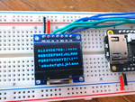
endWe now have all our text rows:
The Progress Bar Row
The last three rows have all outputted an ASCII character, and then we used the text engine to convert the ascii characters into pixels. This fourth row will show one way we can combine both text and direct pixel data onto the screen.
For this row we will take the counter value and convert it to a progress bar representation.
If our progress bar takes up the full screen width then it is 128 pixels wide, if the value we are trying to represent has 256 values then our progress resolution is 1 pixel width for each two values. So we can simply divide the value by two (shift off the LSB) and that would be the number of columns we are supposed to fill in our progress bar.
A simple progress bar might look something like this:
module progressRow(
    input clk,
    input [7:0] value,
    input [9:0] pixelAddress,
    output [7:0] outByte
);
    reg [7:0] outByteReg;
    wire [6:0] column;

    assign column  = pixelAddress[6:0];

    always @(posedge clk) begin
        if (column > value[7:1])
            outByteReg <= 8'b00000000;
        else
            outByteReg <= 8'b11111111;
    end

    assign outByte = outByteReg;
endmodule
For each column index we check if it is bigger then the value divided by two (we do the division by just removing bit 0). If the column index is bigger, then we don't want this column to be filled in so we output a column of zeros to make those pixels not light up, otherwise we can output 255 or all 1s to light up the entire column.
This will work but it will make the progress bar simply be a rectangle 16 pixels tall, we can class it up a bit by shrinking the bar to not take up the full 16 pixels and by adding a border to our progress bar:
reg [7:0] bar, border;
wire topRow;

assign topRow = !pixelAddress[7];
We can add registers to store the pixel column for a filled column and the pixel column for an empty column/border, we also need the topRow variable since we split our screen into 4 rows and there are 8 physical columns of pixels, we take up two physical rows. So we have the topRow variable to tell us if we are on the top row or bottom row. We can use this information to center the progress bar between the two rows. For the top row we will output the top half of the progress bar and for the bottom row we will output the other half.
We can change our always block to look like the following:
always @(posedge clk) begin
    if (topRow) begin
        case (column)
            0, 127: begin
                bar = 8'b11000000;
                border = 8'b110000000;
            end
            1, 126: begin
                bar = 8'b11100000;
                border = 8'b01100000;
            end
            2, 125: begin
                bar = 8'b11100000;
                border = 8'b00110000;
            end
            default: begin
                bar = 8'b11110000;
                border = 8'b00010000;
            end
        endcase
    end
    else begin
        case (column)
            0, 127: begin
                bar = 8'b00000011;
                border = 8'b00000011;
            end
            1, 126: begin
                bar = 8'b00000111;
                border = 8'b00000110;
            end
            2, 125: begin
                bar = 8'b00000111;
                border = 8'b00001100;
            end
            default: begin
                bar = 8'b00001111;
                border = 8'b00001000;
            end
        endcase
    end

    if (column > value[7:1])
        outByteReg <= border;
    else
        outByteReg <= bar;
end
This might look like a lot at first but let's take a look at the default for each of the switch statements, we can see if we are in topRow we set the bar to be 11110000 to light up the bottom 4 pixels of the column and for the bottom row we set bar to be 00001111 to light up the top 4 pixels. These will combine and altogether between the two rows we will have 8 pixels lit up.
Looking at the border in both these default cases, you can see it is all the pixels off, except for the last lit up pixel to give the effect of a border.
The rest of the cases are for the first and last columns, in these columns we change the pixels a bit to create rounded corners.
The last if/else statement is like what we had before, but instead of putting all ones or all zeros, we put either the border pixels or filled pixels depending on the same condition as before.
To hook this module up, let's add the following to our top module in top.v:
wire [7:0] progressPixelData;
progressRow row4(
    clk,
    counterValue,
    pixelAddress,
    progressPixelData
);
It's worth noting that here we are not using the character address anymore but the actual pixelAddress from the screen. That is because we want to receive / decide what to draw for all 128 columns independently as we are drawing graphics. As apposed to the character address which only goes through 16 indices for characters. The output here is also the actual pixel data and not the ASCII value.
So to connect this row we don't change the always block like for the previous row, since that block decides what goes into the text engine. Here we want to change what goes to the screen. So we can replace the row where we assigned chosenPixelData with the following:
assign chosenPixelData = (rowNumber == 3) ? progressPixelData : textPixelData;So if we are on the last row we will send the progress bar data to the screen, otherwise we will connect the output of the text engine.
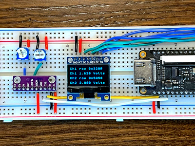
That should be the last thing we needed, and our project should now be fully functional. Changing WAIT_TIME in the counterM module to something smaller:
localparam WAIT_TIME = 1000000;And running the project should give you something like this:
Conclusion
In this article we wrapped up our OLED mini project, combining our screen driver and text engine with different data visualization techniques. We also looked at a way of combining both text and pixel data into a single project.
Thank you for reading, I hope you enjoyed like always all the code can be found in our tang nano 9k series Github repo.
If you have any questions feel free to ask below in the comment section or on twitter here.
And if you would like to purchase any of the items used in this series and support the site you can visit our store here.

