

In this article, we will dive into LED pixel matrix panels and create some drivers to interface with this type of screen. The type of panel we are going to be using is sometimes called a HUB75 panel based on the interface and comes in a variety of sizes and densities.
This article was developed by Chandler Klüser and follows his exploration of this protocol.
What is HUB75 ?
It sounds like a simple question, and based on the popularity of these boards you would think it would be easy to find the source. However, it seems HUB75 is a protocol that has emerged from the LED panel industry without being formally standardized by any specific party.
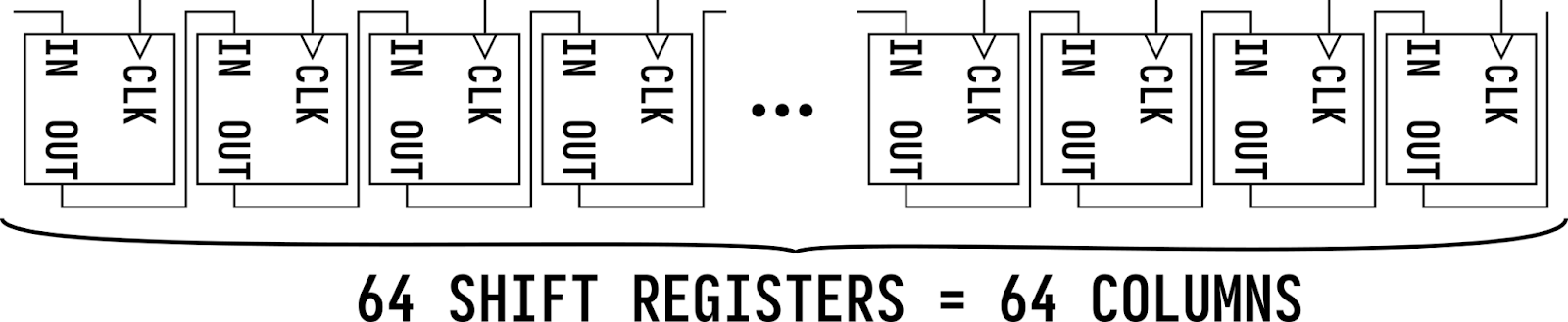
These LED matrix panels essentially work by having a row of pixels shifted into a shift register and then a demultiplexer to select which of the rows the data should be displayed on. By altering through the rows quickly you can draw an entire image to the panel.
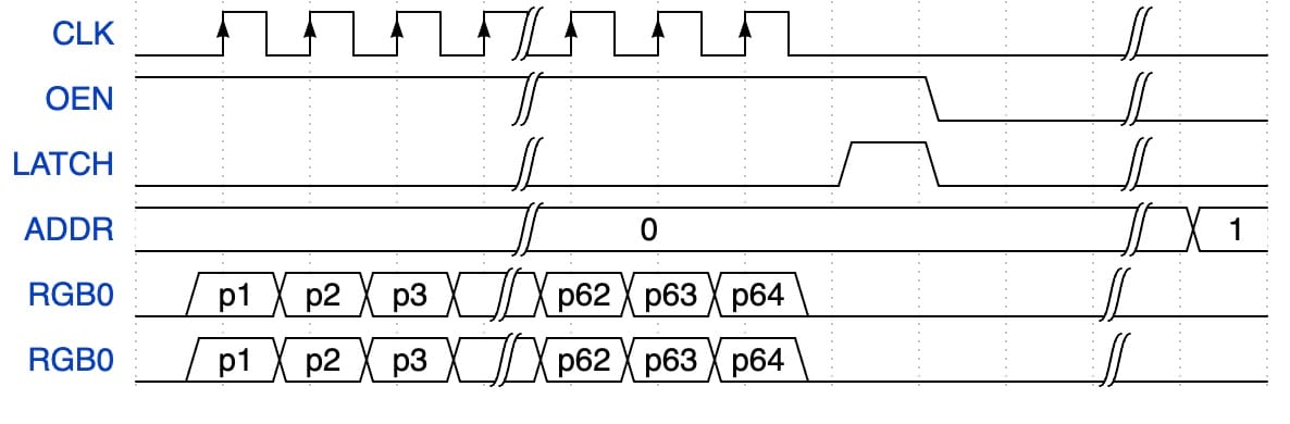
So essentially you select a row using the address bits, then shift in a pixel value for each pixel in the row. With the row data pushed in, you latch the data to store and output the value of the shift register to the LED of that row; repeating the cycle per row.
Each pixel is an RGB pixel, meaning for each pixel you output 3 bits one for if the red LED in the pixel should be lit, one for green, and one for blue. In this article, we will be using a 64x32 LED panel, so we need to shift in 64 RGB values for each line.
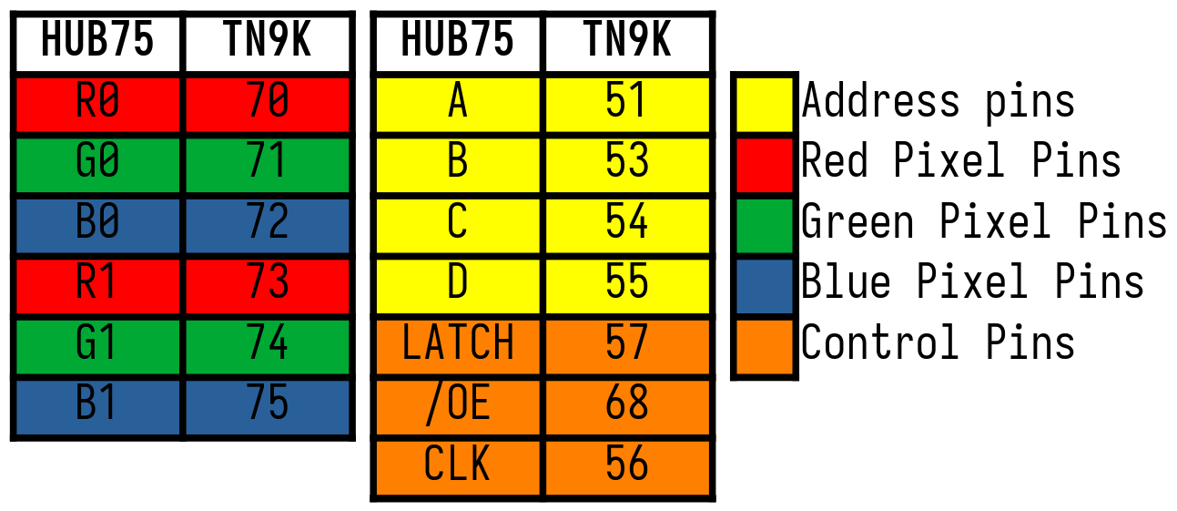
With 3 bits of color data per pixel, you essentially have 8 possible color options per update just like the ZX Spectrum. The HUB75 connector to interface this type of screen has the following pinout:

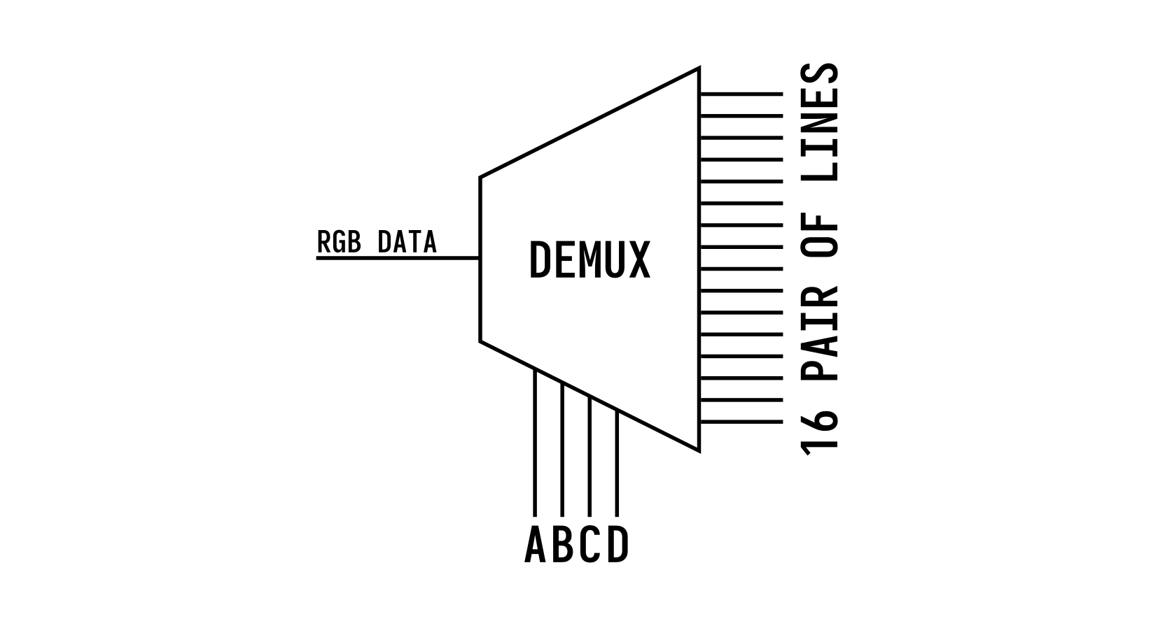
Instead of going through 32 lines, you have 2 channels of pixels RGB0 and RGB1 making each update draw two lines at a time, giving you only 16 lines to address. The addressing is done using the A, B, C, and D inputs. The way the 2 channels of pixels work, is that the top half of the board is controlled by RGB0 and the bottom half of the board is updated by RGB1 so when you update the first line you also update line 17, and then line 2 and line 18, etc.
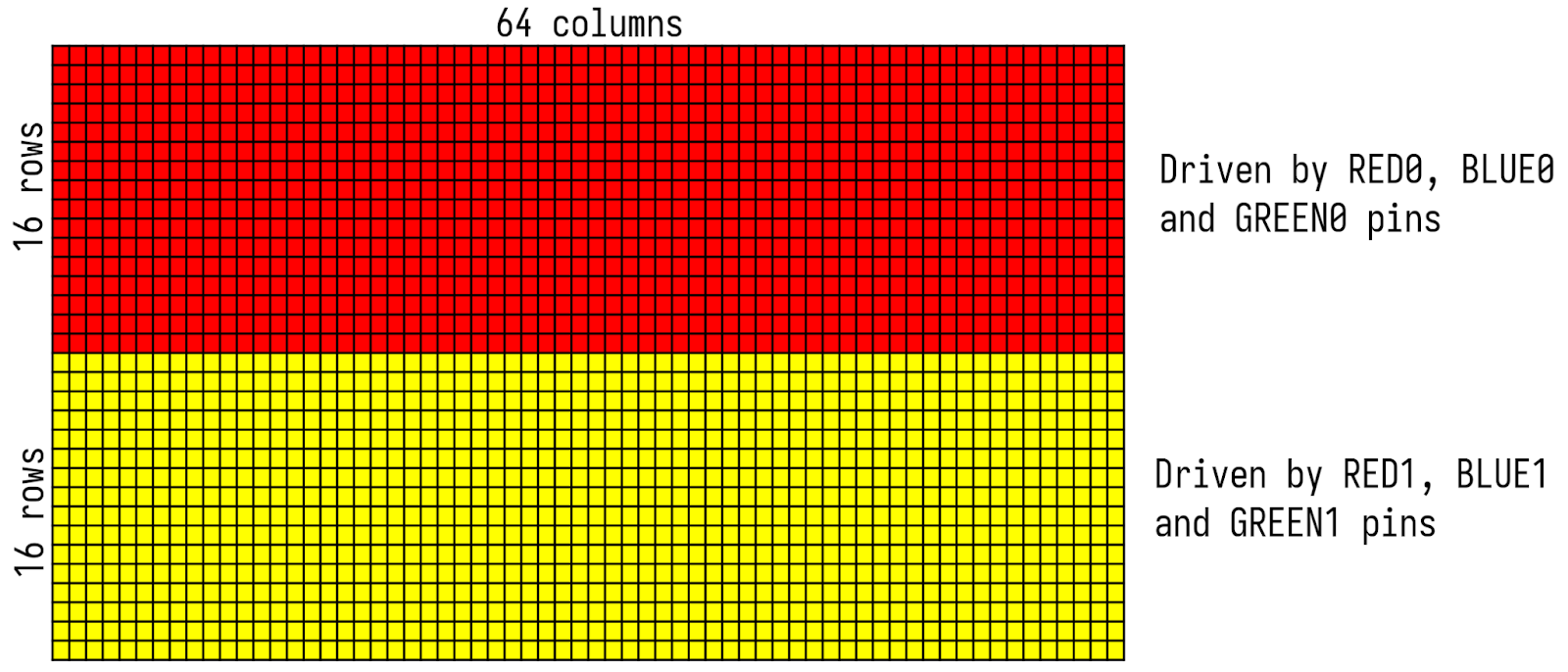
So again you select 1 of the 16 address lines using A, B, C, and D which will internally connect the 2 RGB channels to the correct pair.
Other than that we have a CLK signal which is used to shift data into the shift register chain and a LATCH signal to move the shifted-in data to the output (pixels). This allows you to first shift out the entire row before updating the screen (which would cause flickering / scrolling).
Finally OE or Output Enable is used as the global output switch to turn on and off all the pixels of the screen. This can also be modulated to control the brightness intensity of the output. These screens, given enough current, can be quite bright so by limiting the amount of time the output is enabled (OE is usually active low) you can dial in the brightness and current consumption.
Another feature of these boards is their ability to be daisy-chained extending the pixel count to any arbitrary size.
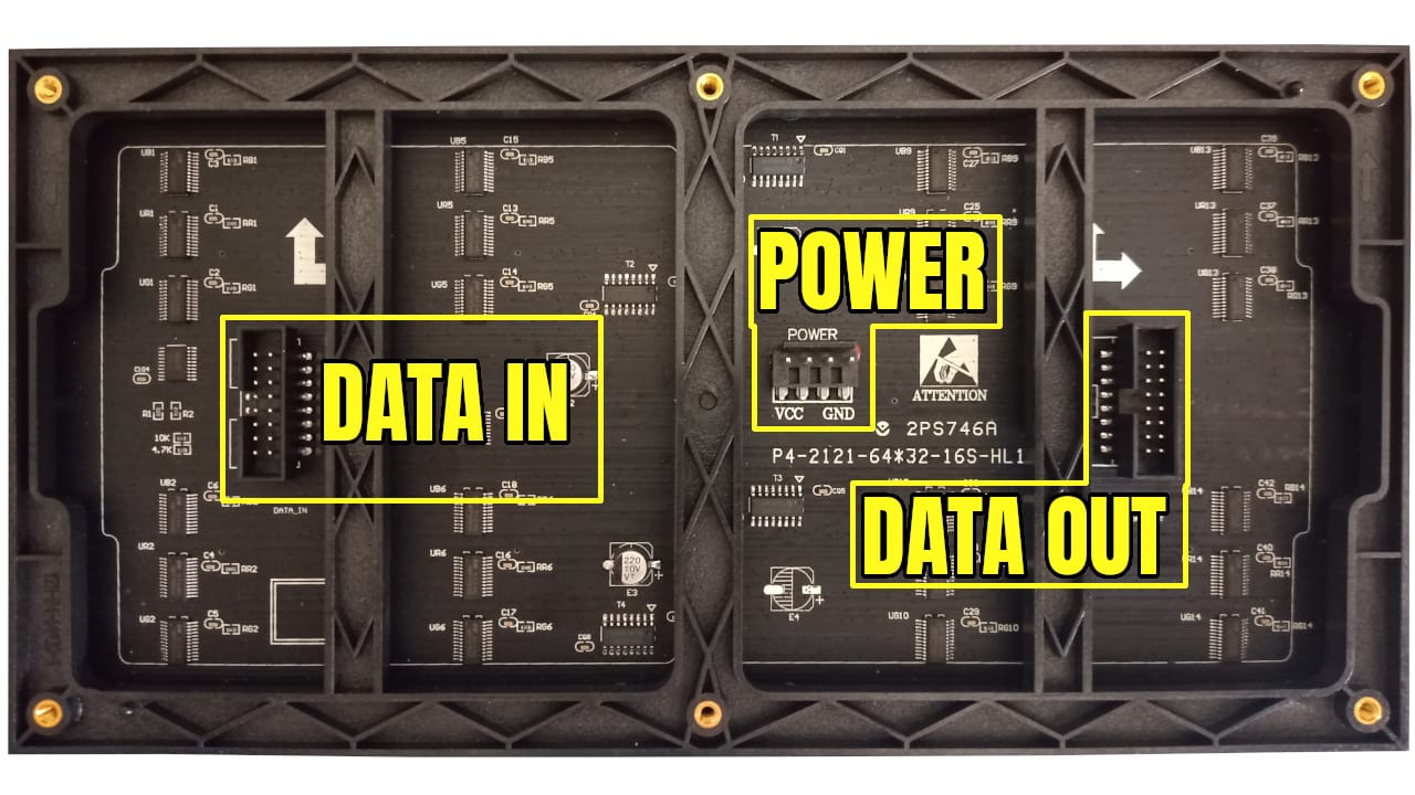
So for 2 boards, you would just shift in 128 pixel values instead of 64 and everything else would stay the same making it easier to scale up.
With that theory out of the way, we can start with electrically connecting the Tang Nano to this panel.
The Electronics
Luckily not too much is needed, the logic interface can be run directly via 3.3V so only some sort of connector is needed to be wired up and no other passive components are required.
In this example, we will be wiring it up like so, but any pins (in the 3.3v banks) could work for this:
Standard header pins can be used to create a 2x8 connector for the panel's cable again the pinout for the connector should be the following:
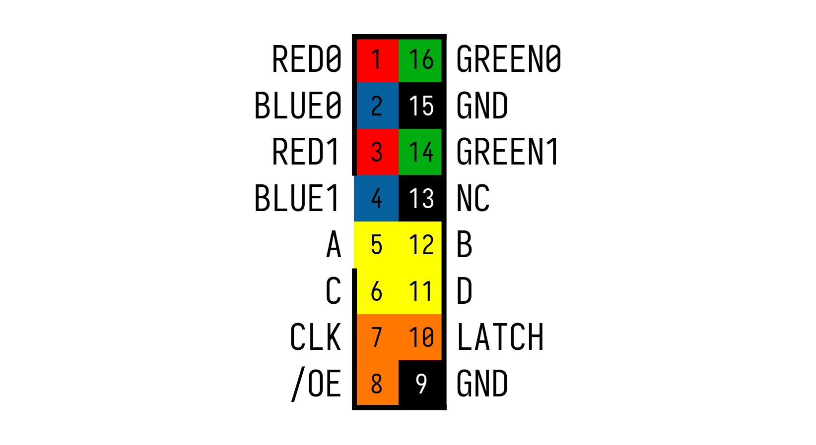
The only important thing to remember is the direction of the header, these ribbon cables usually have a key or outdent which allows it to slot in, in the correct direction. This can be seen in the image above next to the BLUE1 and A pins there is a slot. When creating a connector using standard male headers, you won't have a special key and you need to keep track of this manually.
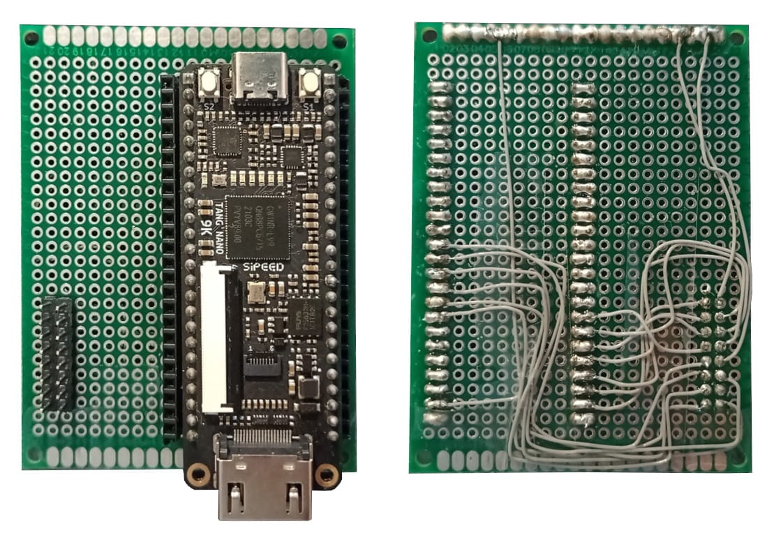
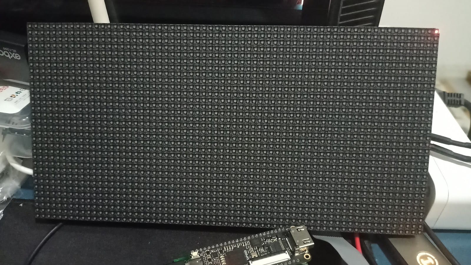
Once wired up you should have something like the following:
This will allow you to connect up the LED panel to the TangNano directly like so:
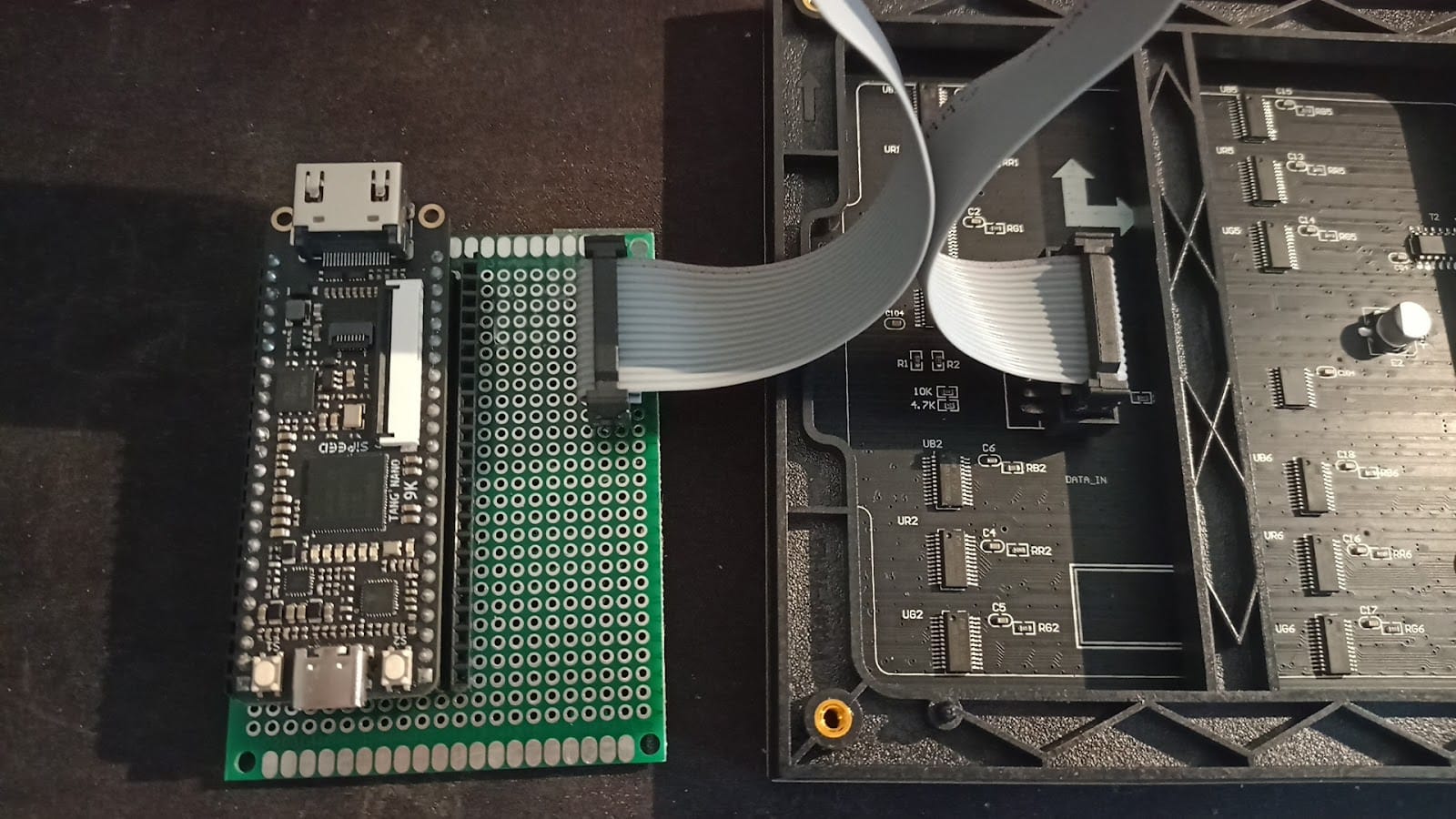
Other than that, the LED panel also requires hooking up the power signal to its external power pins. The voltage range is usually pretty flexible and can run even at 3.3v but ideally should be run at around 4-5v. The panel can consume a lot of power if all the LEDs are lit (I was reaching 1-2 amps with PWM) so a sufficient power supply should be used.
At lower voltages (3.3v) I also noticed more flickering artifacts on unlit (black) pixels, but other than that the voltage mostly affects the brightness of the colors.
For the TangNano itself, we will be powering it with the USB cable so nothing special there to setup. With the electronics done, we can now start implementing our first LED Matrix driver.
HUB75 Hello World
As we saw, to drive the HUB75 LED panel, we need to select a row (row pair) using the address lines, shift in 64-pixel values per channel, and then latch the data to display it on the screen.
So before we get into anything fancy, let's try lighting up a single pixel on a single line.
Let's start by creating a module:
module hub75_demo_driver(
    input           clk,
    input           rst,
    output reg[3:0] ADDR,
    output reg      OE,
    output reg      LATCH,
    output[2:0]     RGB0,
    output[2:0]     RGB1,
    output          clk_out
);
    localparam PIXEL_COLUMNS = 64; // screen width in pixels
    localparam PIXEL_LINES   = 16; // screen height in pixels/2

endmodule
Our module receives two input ports the main clk signal and the rst port which is connected to the reset button. Other than that all the other ports are the outputs of the LED panel.
ADDR is a 4-bit port connected to the A, B, C, and D inputs of the LED panel, OE and LATCH are connected to their corresponding control lines. Next, we have RGB0 that controls the top half of the screen and RGB1 that controls the rows in the bottom half of the screen. Finally, clk_out is the signal to control the clock of the LED panels shift registers, every pulse of the clk_out port will shift one pixel into the screen.
Inside the module, we define two local parameter constants, one to store the number of pixels per column, and one to store the number of row pairs the screen has.
Next, let's set up some registers:
reg[6:0] counter = 0;

assign ADDR = 4'b0000;
assign RGB0 = (counter==63) ? 3'b001 : 3'b000;
assign RGB1 = 3'b000;
We will use the 7-bit counter as a pixel counter to know where we are in the frame. In terms of address, we will hard-code this to a value of: 0, only displaying data on the first row pair. For the pixel color pins, we will set the bottom half of the screen to always 0 so it will stay not lit up, and for the top half of the screen we will only light up the last shifted in pixel (when counter == 63). We set RGB0 to 001 meaning only the least significant (red) subpixel will be lit.
Next, let's create some helper modules to take care of the other control signals clk_out and OE:
module clock_divisor (
    input       clk,
    output  clk_out
);

    reg[11:0] counter = 0;
    assign clk_out = counter[11];
    always @(negedge clk) counter = counter + 1;
endmodule
In this module, we are simply dividing up the clock by a factor of 4096 giving us about 6.5Khz (27Mhz/4096), updating a line requires about 66 clock cycles (64-pixel shifts and two for latching) so we will be at around 100fps for a single line.
This division is arbitrary, the screen can be updated a lot faster than this, because there is no standard it is hard to say what speed will work for you, but you can play with this value lowering the pixel count from 12-bits to 6-bits or even smaller to play with the speed. The HUB75 board I received was able to even run at the full 27Mhz but that is usually not required as it would give you about 25,000 FPS for an entire screen update. Updating the screen too fast, even if it handles it, shortens the resolution of the screen brightness as the entire frame is smaller so less time/resolution to be on / off during a cycle.
Speaking of screen brightness, we can play with the duty cycle of the OE pin to adjust the percentage of time the screen is lit up.
module oe_controller(
    input      clk,
    input      rst,
    input[6:0] cnt,
    output reg  OE
);
    localparam OE_INTENSITY  =  16;
    always @(negedge clk) begin
        if (!rst) begin
            OE      = 1;
        end else begin
            if (cnt<OE_INTENSITY) OE = 0; else OE = 1;
        end
    end
endmodule
OE is usually an active low signal, so during a reset we will set it high, blanking the screen, and other than that we will check where we are in the process from 0-64 pixels currently being shifted in, and if the current pixel count is lower then the intensity we will light up the screen, otherwise it will be turned off.
So a higher value of OE_INTENSITY means the current row on the screen will be powered for longer. It doesn't actually have to do with the pixels, being shifted in, as all pixels in a row update at the same time (when the LATCH pin is pulled high) so we are using the pixel counter only as a measure for the duration in time of a row update.
With these two modules, we can go back to our main module and integrate them:
wire clk_master;
clock_divisor clkdiv(
    .clk(clk),
    .clk_out(clk_master)
);
assign clk_out = (counter<PIXEL_COLUMNS) ? clk_master : 1;

oe_controller oe_ctrl(
   .clk(clk_master),
   .rst(rst),
   .cnt(counter),
   .OE(OE)
);
For the latch cycle at the end of a row, we will leave the clock high, but everywhere else we are directly connecting the external shift registers clock to this clock divider.
As for the OE (output enable) pin, we connect it to our controller module, along with our subdivided clock and the pixel counter we created earlier.
reg LAT_EN = 1;
always @(negedge clk_master) begin
    if (!rst) begin
        LATCH         <= 0;
        LAT_EN        <= 1;
        counter       <= 7'd0;
    end else begin
        counter <= counter + 7'd1;

        if (counter==PIXEL_COLUMNS & LAT_EN) begin
            LATCH <= 1;
        end else if (counter==PIXEL_COLUMNS+1 & LAT_EN) begin
            LATCH        <= 0;
            counter      <= 7'd0;
            LAT_EN       <=    0;
        end
    end
end
We start with our flag to update LATCH set high (LAT_EN) We then have our main always block which will update our pixel counter and control the latch signal.
For 64 cycles we don't need to do anything, as we are not changing colors here per pixel, after all the pixels have been shifted in we set the LATCH pin high, and then on the next clock-divided cycle we set the LATCH back low and disable the LAT_EN flag, causing us to only do a single update to the screen.
The Constraints File
Before running our example driver we need to create our .cst file, as per the pinout above, we are connecting it as follows:
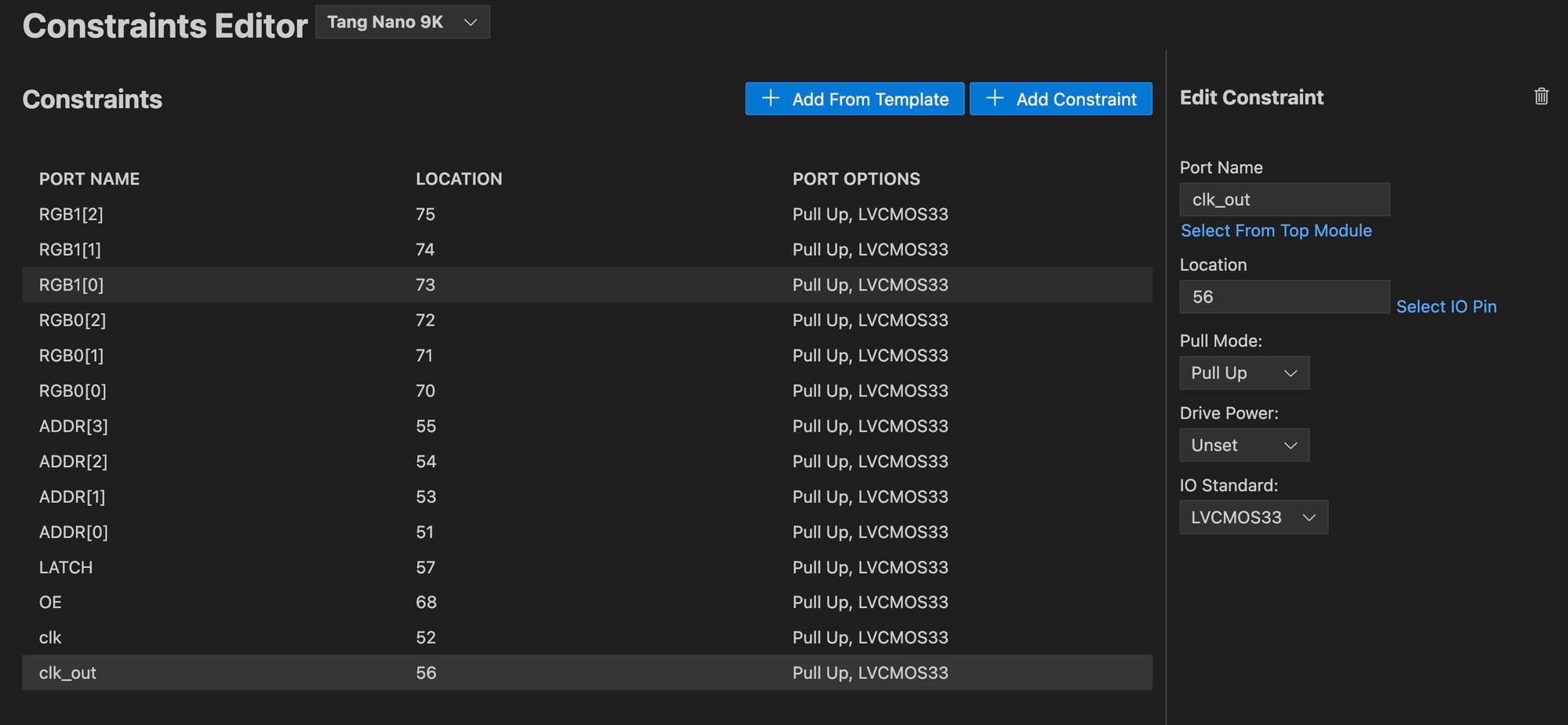
If you are creating the .cst manually then in text form, it would be:
IO_LOC  "RGB1[2]" 75;
IO_PORT "RGB1[2]" IO_TYPE=LVCMOS33 PULL_MODE=UP;

IO_LOC  "RGB1[1]" 74;
IO_PORT "RGB1[1]" IO_TYPE=LVCMOS33 PULL_MODE=UP;

IO_LOC  "RGB1[0]" 73;
IO_PORT "RGB1[0]" IO_TYPE=LVCMOS33 PULL_MODE=UP;

IO_LOC  "RGB0[2]" 72;
IO_PORT "RGB0[2]" IO_TYPE=LVCMOS33 PULL_MODE=UP;

IO_LOC  "RGB0[1]" 71;
IO_PORT "RGB0[1]" IO_TYPE=LVCMOS33 PULL_MODE=UP;

IO_LOC  "RGB0[0]" 70;
IO_PORT "RGB0[0]" IO_TYPE=LVCMOS33 PULL_MODE=UP;

IO_LOC  "ADDR[3]" 55;
IO_PORT "ADDR[3]" IO_TYPE=LVCMOS33 PULL_MODE=UP;

IO_LOC  "ADDR[2]" 54;
IO_PORT "ADDR[2]" IO_TYPE=LVCMOS33 PULL_MODE=UP;

IO_LOC  "ADDR[1]" 53;
IO_PORT "ADDR[1]" IO_TYPE=LVCMOS33 PULL_MODE=UP;

IO_LOC  "ADDR[0]" 51;
IO_PORT "ADDR[0]" IO_TYPE=LVCMOS33 PULL_MODE=UP;

IO_LOC  "LATCH" 57;
IO_PORT "LATCH" IO_TYPE=LVCMOS33 PULL_MODE=UP;

IO_LOC  "OE" 68;
IO_PORT "OE" IO_TYPE=LVCMOS33 PULL_MODE=UP;

IO_LOC  "clk" 52;
IO_PORT "clk" IO_TYPE=LVCMOS33 PULL_MODE=UP;

IO_LOC  "clk_out" 56;
IO_PORT "clk_out" IO_TYPE=LVCMOS33 PULL_MODE=UP;
Not much to go over, we have pin 52 which is our main clock, and everything else is the pins connected to our HUB75 connector.
With this we can now run our module and you should see a single pixel lit up:
If instead you only see the pixel flash and then turn it off this is ok, after testing multiple boards it seems some boards don't actually, allow you to pulse the OE pin and will only display the data on the first OE pulse requiring you to change address lines before displaying a line again.
The issue is sometimes even more subtle than that, as some boards don't allow you to keep OE low all the time, but rather precisely control when in the cycle it should be on or off in regards to the other signals. For example one of the screens required changing the address line to re-output light, so toggling between two row addresses each frame caused it to work.
This is another disadvantage in the lack of standardization on these screens, but for most examples, you will be updating the entire screen in each frame anyway so it will work mostly as expected.
With the proof of concept out of the way, we can now move on to displaying an entire image.
Displaying an Image
To display a full image on the screen we simply need to do the same process as updating a single line, just 16 times. We also want to dynamically set the RGB value of each pixel based on our image.
The easiest way to do this is with a frame buffer. By storing the entire image in memory, we can look up any RGB value we need, for both the top half of the screen and the bottom half, based on our pixel counter and address lines, controlling the RGB output.
We have 64x32 pixels and for each pixel, we have 3 bits of data giving us a total minimum framebuffer size of 768 bytes.
To make it easy to look up, instead of storing the data in bytes, we will set up a ROM with 1024 3-bit values, which is 64 pixels x 16 rows x 3 bits per pixel, which is what we need for each half of the screen.
The choice of having two separate ROMs for each half of the screen versus a single ROM for both lines is an arbitrary decision and just makes the creation of the ROM slightly simpler instead of pairing lines, this is negligible though as we could have stored 1024 6-bit values where each value stores a pixel for both the top and bottom half.
To load our data we can use things like readmemh or readmemb like we have done in the past, but for this example, we will generate a static verilog ROM to showcase another method.
So let's start with a script that will take in an image and convert it into the ROMs we will need to display an image.
Converting Image to ROM
The script we need to create needs to do a number of things:
- Load in an image file
- Resize to dimensions of LED panel
- Quantize colors to our 3-bit space
- Generate Verilog ROM files
We will be using node.js but any language can be used. To get started in a terminal window inside a new folder you can run npm init pressing enter multiple times to generate a new package.json so we can keep track of dependencies locally.
Next, you can run npm install sharp which will install an image-processing library called sharp for node.js that will allow us to process images and extract their pixels. Finally, we can create the script file convert.js where we will go through the steps above:
const sharp = require('sharp');
const fs = require('fs');

// usage: node convert.js <image_path>

const imagePath = process.argv[2];
const imageWidth = 64;
const imageHeight = 32;
We start by loading in the sharp library for working with images and then the fs built-in library for working with the filesystem (to save the Verilog output files). Next, we will accept the image path as a CLI argument and we define the screen size. argv is a variable that stores the command run along with it's arguments, index 0 would store the application being run in our case the Node.js interpreter node, index 1 would be our script (convert.js) which we are passing to be interpreted, finally index 2 would be the first argument to our script which in our case will be the image to convert.
Images usually store data as 8-bit colors per channel, and we only have 1 bit per color channel, so we will need a way to quantize the color value from the input source color to the destination color of our screen. To do this we will see if the color channel is above a threshold (in our case 128/256 which is 50%) if the channel is above 50% on we will light it up on our panel.
function quantizeColor(value) {
  return value >= 128 ? 1 : 0;
}

function convertTo3Bit(r, g, b) {
  return (quantizeColor(b) << 2) | (quantizeColor(g) << 1) | quantizeColor(r);
}
The convertTo3Bit function just combines the 3 states into a single 3-bit value, red is our least significant bit and blue is our most significant bit, based on how we set up our constraints.
With these two helper functions, we can create the function to process our image:
async function processImage() {
  try {
    const image = sharp(imagePath);
    const { data, info } = await image
      .resize(imageWidth, imageHeight)
      .raw()
      .toBuffer({ resolveWithObject: true });

    let topHalf = [];
    let bottomHalf = [];

    for (let y = 0; y < imageHeight; y++) {
      for (let x = 0; x < imageWidth; x++) {
        const idx = (imageWidth * y + x) * info.channels;
        const r = data[idx];
        const g = data[idx + 1];
        const b = data[idx + 2];
        const value = convertTo3Bit(r, g, b);

        if (y < imageHeight / 2) {
          topHalf.push(value);
        } else {
          bottomHalf.push(value);
        }
      }
    }

    return { topHalf, bottomHalf };
  } catch (error) {
    console.error('Error processing image:', error);
  }
}
The function starts by loading in the image by path, we then resize the image to the correct size and get the raw pixels bytes out. The format of this data is a long array where the first element is the red 8-bit value of the first pixel, then the green, etc continuing for each channel and pixel in the source image.
The code creates an array to store the bytes for the top half and bottom half of the screen separately. For each pixel in the image we get the RGB values, convert them to a 3-bit value using our helper functions, and then store it either in the topHalf array or bottomHalf array based on the current line.
With the image processed and converted into the bytes that we need, we can now generate a ROM file using this data for each half:
function generateVerilogROM(array, moduleName) {
    let verilogCode = `module ${moduleName}(input clk, input [9:0] addr, output reg [2:0] data = 0);\n\n`;
    verilogCode += `    always @(*) begin\n`;
    verilogCode += `        case (addr)\n`;

    array.forEach((value, index) => {
        let binaryAddress = index.toString(2).padStart(10, '0'); // 10-bit binary address
        let binaryValue = value.toString(2).padStart(3, '0'); // 3-bit binary value
        verilogCode += `            10'b${binaryAddress}: data <= 3'b${binaryValue};\n`;
    });

    verilogCode += `            default: data = 3'b000;\n`;
    verilogCode += `        endcase\n`;
    verilogCode += `    end\n`;
    verilogCode += `endmodule\n`;

    return verilogCode;
}
This function accepts an array of bits from the previous function, along with a name for the generated Verilog module. This generated module has 3 ports, a clock signal, a 10-bit address input, and a 3-bit data output. The rest of the module is an always block where based on the address it will set the output with a hardcoded value from our byte array.
For example, a generated file could look something like the following:
module ROMTop(
    input clk,
    input [9:0] addr,
    output reg [2:0] data = 0
);

    always @(*) begin
        case (addr)
            10'b0000000000: data <= 3'b000;
            10'b0000000001: data <= 3'b001;
            10'b0000000010: data <= 3'b001;
            // ... all other addresses
            10'b1111111110: data <= 3'b000;
            10'b1111111111: data <= 3'b000;
            default: data <= 3'b000;
        endcase
    end
endmodule
To wrap up our node.js script, we just need to wire everything up with a main function:
async function main() {
    const { topHalf, bottomHalf } = await processImage();

    const topHalfVerilog = generateVerilogROM(topHalf, 'ROMTop');
    const bottomHalfVerilog = generateVerilogROM(bottomHalf, 'ROMBottom');

    fs.writeFileSync('top_half_rom.v', topHalfVerilog);
    fs.writeFileSync('bottom_half_rom.v', bottomHalfVerilog);
    console.log('Generated 2 Verilog ROM files');
}
main();
This function calls the other two functions generating the Verilog text for both ROMs, it then stores them as files using the fs (filesystem) built-in library. With the script ready you can run it in a terminal with:
node convert.js ./yt_count.pngReplacing yt_count.png with the path to your own image file. You should see that two Verilog files were created in the directory you ran the script from. With these files created, we can start creating a new driver which will display the image.
Image Hub75 Driver
We will be using the same clock_divisor from the proof of concept, but this time instead of having static color values for the RGB signals we will want to dynamically load them based on the current pixel being shifted out. You may want to make your clock divisor a bit faster since we will be updating the entire screen instead of just a row:
module clock_divisor (
    input  wire clk,
    output wire clk_out
);
    reg[3:0] counter = 0;
    assign clk_out = counter[3];
    always @(posedge clk) counter <= counter + 1;
endmodule
To retrieve the pixel data we will create a framebuffer module to interface with the two generated ROMs:
module framebuffer(
    input  wire       clk,    // main clock
    input  wire [5:0] column, // column index (6 bits for 64 pixels)
    input  wire [3:0] ADDR,   // ADDR input
    output wire [2:0] RGB0,   // RGB0 output
    output wire [2:0] RGB1    // RGB1 output
);
    wire[9:0] addr_rom;
    assign addr_rom = {ADDR, column};

    ROMTop  rom_low(.clk(clk), .addr(addr_rom),.data(RGB0));
    ROMBottom rom_high(.clk(clk), .addr(addr_rom),.data(RGB1));
endmodule
The module receives the current column and address, where column is the pixel index in the x direction which is a value between 0-63 and the address lines is the row number which has a range of 0-15 combining these two gives us a 10-bit index between 0-1023 that we can use to index each of the ROMs' values. We then output the RGB values for each line directly from the ROMs.
Next, we can create our main module:
module hub75_image_driver(
    input  wire       clk,
    output reg  [3:0] ADDR  = 4'd0,
    output reg        OE    = 1'd1,
    output reg        LATCH = 1'd0,
    output wire [2:0] RGB0,
    output wire [2:0] RGB1,
    output reg        clk_out = 1'd0
);
    localparam PIXEL_COLUMNS = 64;

    reg [6:0] pixelCounter = 7'd0;
    reg [4:0] displayCounter = 5'd0;

    wire clk_master;
    clock_divisor clkdiv(.clk(clk), .clk_out(clk_master));
endmodule
So far, it is pretty similar to the previous driver, we have a counter for the current pixel, a counter for the OE signal display time and our clock divider.
Connecting the RGB signals to our framebuffer module is also pretty straightforward:
framebuffer buffer(
    .clk(clk),
    .column(pixelCounter[5:0]),
    .ADDR(ADDR),
    .RGB0(RGB0),
    .RGB1(RGB1)
);
Finally our modified state machine for refreshing the entire screen instead of a single line:
localparam SHIFT_DATA = 0;
localparam LATCH_DATA = 1;
localparam SHOW_PIXELS = 2;
localparam SHIFT_ADDR = 3;

reg [1:0] state = SHIFT_DATA;

always @(posedge clk_master) begin
    case(state)
        // states here
    endcase
end
The first state is to shift out the 64 pixels per line:
SHIFT_DATA: begin
    if (~clk_out) begin
        clk_out <= 1'd1;
    end else begin
        clk_out <= 1'd0;
        if (pixelCounter == PIXEL_COLUMNS-1) begin
            state <= LATCH_DATA;
        end else begin
            pixelCounter <= pixelCounter + 7'd1;
        end
    end
end
Data is updated during the falling edge and read by the panel on the rising edge, so we start with the clock low for one cycle, and then on the next signal when the data is read we update the pixelCounter so that the framebuffer will load the next byte on the next cycle.
If we have completed all 64 pixels we move to the LATCH_DATA state:
LATCH_DATA: begin
    if (~LATCH) begin
        LATCH <= 1'd1;
    end else begin
        LATCH <= 1'd0;
        OE <= 1'd0;
        state <= SHOW_PIXELS;
    end
end
In this state we want to first set the latch signal high - this will latch in the data - and in the next clock cycle, we will set the latch back low and start displaying it to the screen by pulling OE low.
SHOW_PIXELS: begin
    displayCounter <= displayCounter + 5'd1;
    if (displayCounter == 5'd31) begin
        OE <= 1'd1;
        displayCounter <= 5'd0;
        state <= SHIFT_ADDR;
    end
end
The SHOW_PIXELS state simply keeps the OE low for a desired number of frames, the higher the number of frames the brighter the panel will be but the longer each screen update will take. The entire screen update is pretty fast, even with 32 clock-divided signals we still have about 650fps for the entire screen, anything above 60hz should be smooth enough not to have any noticeable flicker.
Where:
<clock speed> - 27Mhz or 27,000,000
<clock divider> - 16
<cycles per line> - 163 = 128 for pixels, 2 for latch, 32 for OE and 1 for addr
<num lines> - 16 line updates (each updates 2 lines)
((27000000/16) / ((128+2+32+1)*16) = 647 updates per second
The final state updates the ADDR register, moving to the next row on the screen:
SHIFT_ADDR: begin
    ADDR <= ADDR + 4'd1;
    pixelCounter <= 7'd0;
    state <= SHIFT_DATA;
end
Running our new driver you should be able to see the image being displayed:
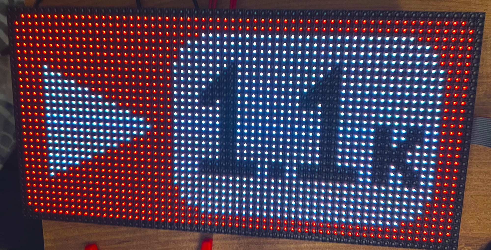
This image references Chandler surpassing 1.1k followers on YouTube, check out his channel here.
Extending the Color Space
Up until now, we have been only using the 8 colors we can get from directly combining the RGB LEDs. For reference, these are the 8 colors:
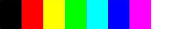
These are the only colors the panel can directly emit, but by rapidly changing between these colors with different proportions of each, we can cause our eyes to perceive a wider spectrum of colors.
The two factors that play a role in the number of colors that can be generated is our pulse resolution and the refresh rate. These two factors kind of work against each other, for example with a higher resolution of 10-bits per channel, would mean we need to go through a period of at least 1024 cycles to accurately give each part of the colors being mixed the correct ratio.
Having a higher period to the cycle means the frequency for the entire sequence goes down. If the frequency goes down too much then it will be very noticeable that different colors are being switched between instead of seeing a blended color.
And when I say it needs to be fast I don't mean like a standard 60 fps, I am talking about the entire color switching sequence needs to fit preferably in a single 60fps update (above 60hz).
So again, higher resolution of color, means more times we need to fully update the screen before we get out a single color, requiring a higher clock speed to get out a frame without flickering.
The next thing we need to do is calculate which of the colors to mix and how. This can be accomplished with a simple counter to know where we are in our cycle.
For example, if we are using 4-bit channels giving us 16 options per channel, then if the value for the red channel is 6, we would light up the red pixel for the first 6 screen updates, and then for the next 10 the red led will be off, giving us the proper ratio by just comparing the channel value to our cycle counter.
You can use the tool below to understand which colors need to be mixed and at what ratio to reach a desired color.
The number of colors grows rapidly as even adding a single bit not only doubles the number of options for a single channel, but that change compounds together with the number of new total options between channels giving an equation as follows:
So with 1 bit of color resolution, we had 8 colors:

By raising our resolution to 2 bits per channel we get 64 colors:
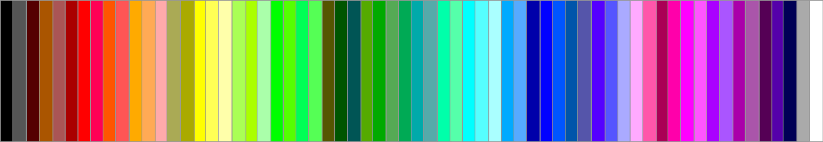
For our next example let's experiment with implementing this 2-bit color into our image viewer.
Generating a 2-bit ROM
Code-wise this is a pretty simple change, we can start off by updating our convert.js script to generate a 6-bit ROM instead of our previous 3-bit version:
function quantizeColor(colorVal) {
  const quantizationLevels = 4;
  const stepSize = 256 / quantizationLevels;

  return Math.floor(colorVal / stepSize);
}

function convertTo6Bit(r, g, b) {
  return (quantizeColor(b) << 4) | (quantizeColor(g) << 2) | quantizeColor(r);
}
The quantization is a bit more generic to support the 4 values per channel, but the general idea is the same as mapping the source 8-bit space into our 2-bit space. Other than that we just need to update the function that generates the Verilog, to output 6 bits instead of 3:
function generateVerilogROM(array, moduleName) {
let verilogCode = `module ${moduleName}(input clk, input [9:0] addr, output reg [5:0] data = 0);\n\n`;
verilogCode += ` always @(posedge clk) begin\n`;
verilogCode += ` case (addr)\n`;
array.forEach((value, index) => {
let binaryAddress = index.toString(2).padStart(10, '0'); // 10-bit binary address
let binaryValue = value.toString(2).padStart(6, '0'); // 6-bit binary value
verilogCode += ` 10'b${binaryAddress}: data <= 6'b${binaryValue};\n`;
});
verilogCode += ` endcase\n`;
verilogCode += ` end\n`;
verilogCode += `endmodule\n`;
return verilogCode;
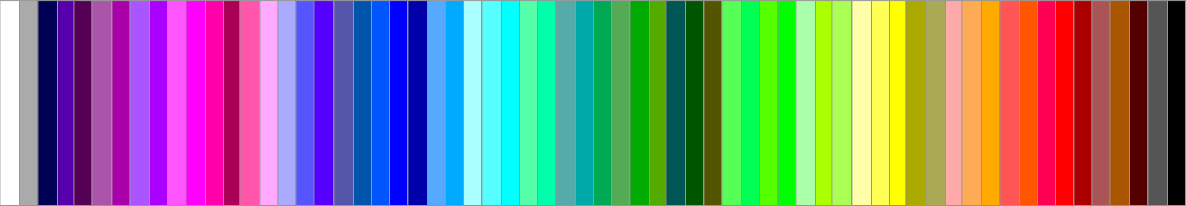
}With that done, you can run the script on an image with node convert.js <path to image> to generate the two new ROM files. You can use the following test image which goes through each of the 2-bit colors:
Implementing the Color Mixing
To implement the color mixing itself we really only need a cycle counter to know where we are in our color cycle. For 2 bits per channel, we need a counter of at least 2 bits to have enough resolution to represent each of the values.
Then on a per-channel basis we can easily just compare the 2-bit color value to the 2-bit counter value and see if the LED should be lit or not.
module framebuffer2Bit(
    input  wire       clk,    // main clock
    input  wire [5:0] column, // column index (6 bits for 64 pixels)
    input  wire [3:0] ADDR,   // ADDR input
    output wire [2:0] RGB0,   // RGB0 output
    output wire [2:0] RGB1,    // RGB1 output
    input wire[1:0] colorCycle
);
    wire[9:0] addr_rom;
    assign addr_rom = {ADDR, column};

    wire [5:0] topRGB;
    wire [5:0] bottomRGB;

    ROMTop  rom_low(.clk(clk), .addr(addr_rom),.data(topRGB));
    ROMBottom rom_high(.clk(clk), .addr(addr_rom),.data(bottomRGB));

    assign RGB0 = {
        (colorCycle < topRGB[5:4]),
        (colorCycle < topRGB[3:2]),
        (colorCycle < topRGB[1:0])
    };
    assign RGB1 = {
        (colorCycle < bottomRGB[5:4]),
        (colorCycle < bottomRGB[3:2]),
        (colorCycle < bottomRGB[1:0])
    };
endmodule
The new frame buffer is almost identical to the previous one except now we have an extra 2-bit input port for the new color cycle counter. Inside we can no longer connect the RGB lines directly to the ROM as they are not the same width anymore.
So we connect new 6-bit wires to the ROMs and the real conversion is what happens next. If we take a look at a single channel from RGB0 for example the red channel:
(colorCycle < topRGB[1:0])We are just comparing our color value with the counter, if our color value is larger then we light the pixel up. Since we only have 4 options per color we can write out the options pretty easily:
| Color Value | Cycle #1 | Cycle #2 | Cycle #3 |
|---|---|---|---|
| 0 | 0 | 0 | 0 |
| 1 | 1 | 0 | 0 |
| 2 | 1 | 1 | 0 |
| 3 | 1 | 1 | 1 |
The number of cycles we need for a complete color is 2n - 1, where n is the number of bits per channel, the -1 is because the first two cases use the same bit for their value.
Next in ourtop module we can replace our existing framebuffer with the 2-bit variant:
reg [1:0] colorCycle = 2'd0;
framebuffer2Bit buffer(
   .clk(clk),
   .column(pixelCounter[5:0]),
   .ADDR(ADDR),
   .RGB0(RGB0),
   .RGB1(RGB1),
   .colorCycle(colorCycle)
);
And then last but not least we need to increment the color cycle counter every time we finish updating the entire screen, which can be done in the SHIFT_ADDR state:
SHIFT_ADDR: begin
    ADDR <= ADDR + 4'd1;
    pixelCounter <= 7'd0;
    state <= SHIFT_DATA;
    if (ADDR == 4'd15) begin
        colorCycle <= colorCycle + 2'd1;
        if (colorCycle == 2'd2) begin
            colorCycle <= 2'd0;
        end
    end
end
Running this now you should be able to see many more colors than what we had before:
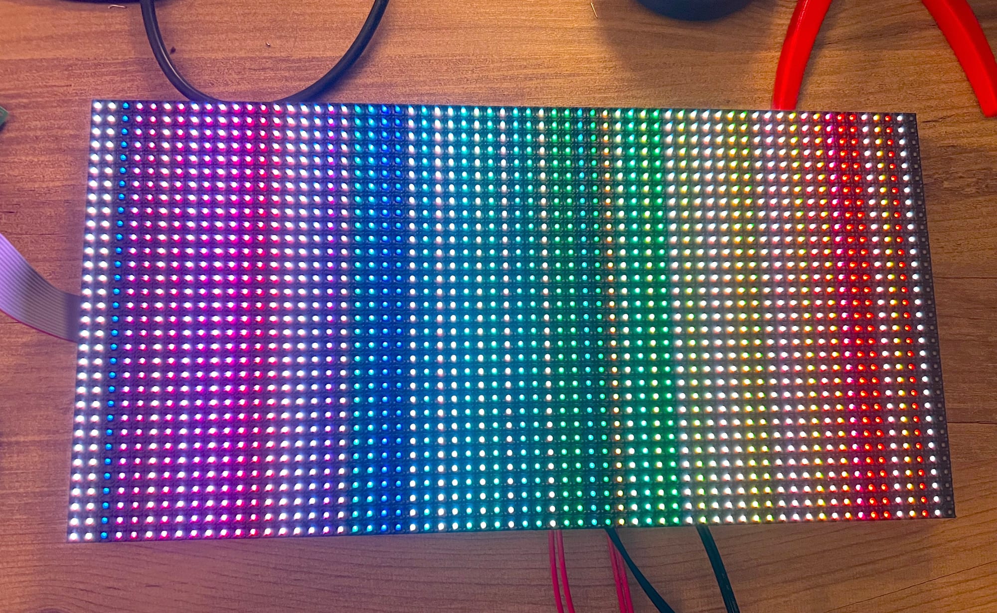
Comparing It again to our reference colors, you can see that we have a pretty close match to the colors, at least the brighter colors:
LEDs emit light, so it's harder to persist a dark color using this method, this causes colors like grey to appear white and brown to look more orange or red. Currently, we are also driving our LEDs linearly for all channels equally, but due to the differences in perceived brightness at different levels and colors, these color values can be adjusted to give them a more calibrated appearance.
This is known as a Gamma correction, which essentially adjusts the brightness of a color to better match how it will be seen by our eyes. I don't think this is worth doing in every application, when remapping the color space you lose some resolution, especially in a small 2-bit configuration. Think of it as selectively darkening colors, but if we only have 64 shades of color and you darken some of them there starts to be more overlap (as we have more dark colors, with fewer options there to represent them using our 2-bits).
With higher color spaces it might make an image look more accurate, but for our example, I didn't find it looked better. To play with this you can use the linear vs gamma functions from the sharp library in our image-to-ROM converter before getting the raw pixels to generate the ROM.
Another option would be to do this in hardware, and instead of using a linear counter to decide when each level is hit, the levels can be spaced differently giving less time for the lower brightnesses.
Conclusion
In this article, we took a look at what is required to interface with the popular HUB75 interface. We created 3 drivers, from lighting up a single pixel to displaying a full image to experimenting with expanding the color space.
Special thanks to Chandler Klüser for developing this project and sharing (and for all the debugging required to understand the inconsistencies of the HUB75 boards). You can check out more of his projects on YouTube here or on GitHub here.
Extending the Project
Here are some ideas on ways you can expand upon the HUB75 projects above:
- Multiple hub75 boards - explore both chaining and stacking boards to create larger rows and columns.
- Higher color channels - you can experiment with different methods of mixing colors or experiment with more bits to get a better color range.
- Scrolling Text Driver - combine the ideas from our project on creating a text engine with the HUB75 panels to display scrolling text from memory. You can then transfer text over UART to display it.
Supporting code for these drivers can be found on Chandler's GitHub repo here and for the color driver you can find the example in our Tang Nano examples repository here.
Thank you for reading I hope you enjoyed it, like always if you have any questions or comments feel free to leave them down below in the comments section or DM us on X @LushayLabs

