

In this article, we will look at composite video, more specifically the NTSC standard, and how we can implement it on the Tang Nano.
We will be following Adam Gastineau who masterfully developed and documented this project, so without further ado, let's get into it.
Composite Video
Composite Video as the name kind of implies is a protocol that combines multiple kinds of data onto the same line. The protocol was developed first for black and white screens that used a ray-gun to blast the front of the screen causing it to light up at the point the ray was pointed at.
The original signal combined two components, luminance (brightness) and sync pulses. The brightness controlled the shade of gray, where 100% luminance would be white and 0% would be black allowing you to create a grayscale image and the sync pulses would be used to tell the ray gun how to move to synchronize it with the signal.
The way it worked was the ray-gun would sweep from the top left corner of the screen moving right, and then when you get to the end of a row it would need something to tell it to go back to the start of the next row. Kind of like a carriage return on a typewriter, the horizontal sync pulse was used for this, at the end of each frame there is also a vertical sync pulse used similarly to cause the ray gun to return to the top left corner to start a new frame.
It's a tiny bit more complicated than that since frames were interlaced in two passes. You would first send all the even lines finishing on a half-line and then return to the top for a second pass to draw all the odd lines. These two passes together create one full frame, but the purpose of the pulses is all the same.
You can think of the ray gun as a sort of light source (LED), the more power you put into it, the brighter it will be (up to the max voltage). We need to both encode sync data and color data, so the protocol splits up the voltage range into two sub-ranges with a small area we can use for sending sync data and the rest of the range used as the brightness range.
For example, typically the complete voltage range is 0v-1v, where a value of zero represents a sync and then there is a small gap to separate the two ranges so it's easier to distinguish between them and then from 0.3v - 1v is the range describing the brightness of a pixel with 0.3v being black and 1v being white.
Now I say "pixel" but we don't really have pixels here, we are dealing with an analog continuous range, controlling a ray gun that is continuously outputting electrons based on the supplied voltage as it moves across the screen. We do have a vertical resolution, for example with the base NTSC standard there are 480 visible vertical lines, which is what we control with the sync pulses, but as to how many horizontal pixels, it would be based on the capabilities of the television itself how many horizontal pixels could be deduced.
Nowadays with composite adapters connected to more modern screen technology, you will have a specific number of pixels which converts to usually something like 600x480, but again this is not part of the base standard and is interpreted differently by each screen.
Drawing Horizontal Lines
To illustrate the above points, let's take a look at how we would draw a single white horizontal line. To do this we would need something like the following:
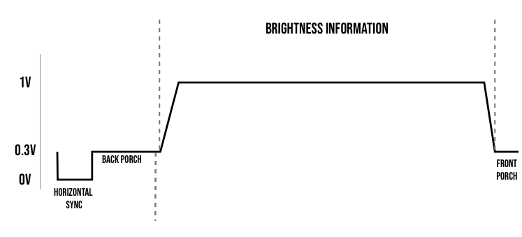
We start with a short pulse at 0v which is called a horizontal sync, it is what would cause the electron beam to retract horizontally starting a new line. After this we have a small section at 0.3v or black roughly the same length as the horizontal sync pulse, this is called the back porch. The purpose of this section is to give the beam time to retrace and stabilize on the other side of the screen.
We then start the color data, here since we are simply drawing a white horizontal line we leave the line at 1v which is the brightest value white. The brightness information lasts for a little under 60 microseconds, and the ray gun would travel horizontally across the screen at this time.
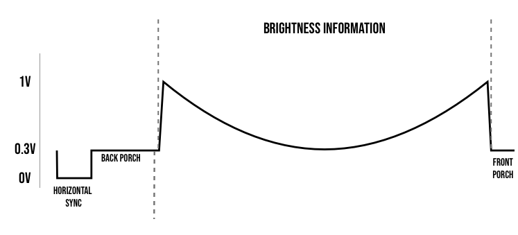
Again during this time, you can put the line at any voltage between 0.3 and 1v to control the brightness at that point along the horizontal. So if we would return the above signal for every line in the image we would get a white screen, and if we wanted to create the following pattern on screen.

Then we would need to send something like the following for each line:
You can play around with the following simulator, and draw in the active area region to update the wave:
To draw an image you would need to keep track of where the "ray gun" is currently on screen, and based on the brightness value of the pixel at that corresponding point, you would need to set the voltage accordingly between 0.3v and 1v.
Finally, at the end of each horizontal line, you have another very small section at 0.3v just to give a little padding between the image and the sync pulse.
Drawing a Frame
Drawing a full frame is just drawing horizontal lines with vertical sync pulses to reset the gun to the top of the screen.
Altogether the NTSC signal can be thought to be comprised of 525 lines, where for interlaced video we first draw the even 262.5 lines and then circle back to draw the odd 262.5 lines.
We talked above about how the screen knew to return to the beginning of the line when it receives a sync pulse, kind of like a carriage return, but we didn't discuss the vertical feed. The CRT laser would be constantly lowered throughout each scanline, moving about half the height of a line in the draw path and the rest during the carriage return.
By resetting the Y position back to the top in the middle of a line, we are essentially half a line higher than where we were on the first pass. Since the first pass started at this Y but at the left side of the screen, once it got to this position it was already lower.
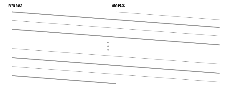
The angle is greatly exaggerated to illustrate the idea, but you can see by resetting the Y position using a vertical pulse mid-line we essentially offset the whole next "frame" by half a vertical line.
An NTSC Frame
For an entire interlaced frame you would need to construct something like this:
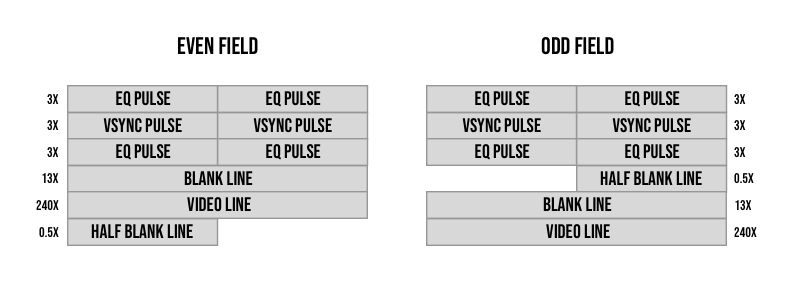
Blank lines are just video lines with the color set to black (0.3v) throughout the entire line. We know how these lines look, they are comprised of a horizontal sync pulse, the back porch, the active video section, and the front porch.
We send 262.5 scanlines per field, and it is worth mentioning that the 0.5 scanline from the first field is the half of the scanline with the horizontal sync pulse and the half scanline of the second field is the end of a scanline without a horizontal sync.
Other than that there are these EQ (equalizing) and vertical sync pulses. Each is exactly half a scan line in length and is comprised of a portion at the sync voltage (0v) and a portion at the blanking voltage (0.3v) (diagram below).
The EQ pulses are short pulses and the vsync pulses are long pulses. Because the only difference between types of syncs is their length (since voltage is already used for other things as we saw), there were typically circuits designed to calculate the length of the pulse. This was commonly done with passive components like capacitors which would build up charge while the pulse is on and discharge when the pulse is off.
We could then trigger a vertical sync when this capacitor reaches a specific voltage level signifying the charge time was the length required for a vertical sync. The problem here is that before the retrace on an even field, we have a full video line, and before the long pulse of the odd field we have a half video line.
This would essentially throw off the calibration or at least make the decoding circuitry more complicated taking into account the differences per field in the charge generated by the previous frame's horizontal sync pulse and the amount of time after that pulse to the time we send the vsync pulse.
The equalizing (short pulses) helps with this by leveling the playing field on both sides. Both before and after the vertical sync pulses no matter the field, we send lines with very short pulses (usually half the size of a horizontal pulse) equalizing the decoding circuitry making the process simpler.
Take a look at these pulses next to our standard horizontal scanline:
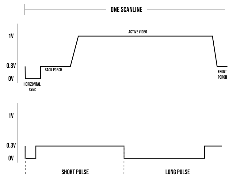
If we were to compare the pulse lengths (the amount of time at 0v for each type of pulse) then the short pulse is about half the time of a horizontal pulse and the long pulse is the length of a half scanline subtracting about the length of a horizontal pulse.
If you want exact numbers, here are some rough estimates:
Full scan line: 63.55µs
Front porch before horizontal pulse: 1.5µs
Horizontal pulse width: 4.76µs
Back porch after horizontal pulse: 4.44µs
Video Section: 52.6µs
Short pulse on width: 2.54µs
Short pulse off width: 29.235µs
Long pulse on width: 27.32µs
Long pulse off width: 4.45µs
Progressive Mode
The original standard we talked about uses a 480i resolution, meaning it has 480 (visible) vertical lines that are rendered interlaced. But understanding the technology and how it works allowed people to "hack" the standard making it easier to implement.
In the base standard, you have things like half-lines and interlacing to deal with and you only get a frame rate of 30fps (and not 60) since it takes two fields per frame.
To get higher refresh rates and simpler drawing logic people removed the half-line causing the frame to not interlace vertically, This meant that the first field and second field were one on top of the other essentially giving you only a single field updating at 60fps.
This comes at the cost of lowering the vertical resolution since each field has only 240 visible lines instead of 480. The lines are also slightly spaced apart without the interlacing causing the retro black lines between rows.
Retro consoles like the NES used this technique and send the following field as their frames:
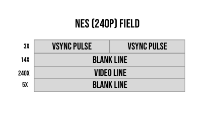
As you can see a lot simpler, you may have noticed, that because we no longer have a difference between the two fields we no longer need the equalizing pulses (short pulses) simplifying it further.
We essentially have the vertical sync and regular horizontal scanlines, and we send a constant 262 fields instead of trying to match the 262.5, but because of the sync pulses (and maybe the almost mechanical nature of the protocol), this seemed to work.
We will be implementing this format of NTSC on the Tang nano. So without further ado let's get into the build.
The Electronics
The first practical issue we need to deal with is generating the analog signal from our FPGA.
One way we can accomplish this is by using a sort of voltage divider via a resistor network. This is cheap, would allow us to enter values in parallel and they are super fast to react, being comprised of only resistors.
If you have seen a resistor ladder (e.g. R-2R) then you probably know where we are going with this, but if not we will start from the beginning.
A voltage divider at its simplest could look something like this.
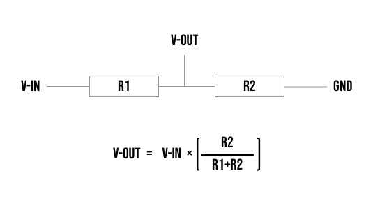
In our case, we have a voltage source of 3.3v so that would be V-In, and if we take for example 1k Ω for R1 and a 2k Ω resistor for R2 We can see that we would get 3.3 * (2/3) or 2.2 volts, exactly 2/3 the voltage.
Resistors in series can be simplified into a single resistor by just combining the resistance values. So our example above would be equivalent to a single 3k Ω resistor between V-in and Gnd. Using Ohm's law we can calculate the current through this circuit as I = V/R or I = 3.3/3000 = 0.0011 amps.
Now going back to the original schematic, we know R1 is 1000 Ω, so to calculate the voltage drop over R1 we can again use ohms law and get V = IR or V = 0.0011 * 1000 = 1.1 volts. If R1 has a voltage drop of 1.1 volts then we can see that the voltage right after is 3.3-1.1 or 2.2 volts, like we got from the formula above.
The last piece of this puzzle is the way resistors behave when they are in parallel. If I have two or more resistors in parallel then to calculate the equivalent resistor that you can use to simplify the circuit you have to take the reciprocal of the sum of reciprocals of each resistor. Quite a mouthful, but essentially you take the reciprocal of each resistor, sum all those numbers up, and then take the reciprocal of the sum.
So for example, if I have 3 resistors Ra, Rb, and Rc all in parallel, then I could essentially replace them with a single resistor R as follows:
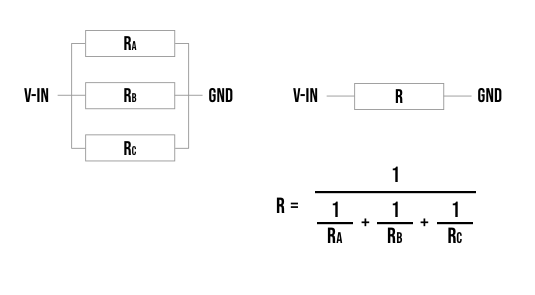
So we know that having two resistors in series divides the voltage proportionally between the two, and we know that adding multiple resistors in parallel decreases the effective resistance.
Composite video has an input impedance of 75 Ω and our signal comes from our voltage source and is attached on the other end to our ground, so the screen itself can act as the basis for the second resistor in our voltage divider R2.
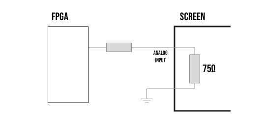
The above setup would only let us output a very specific voltage since the resistor is constant (and we can do 0v).
To get a more dynamic range we add multiple resistors connected on one end to our FPGA's pins and the other end to the composite signal.
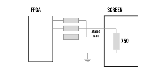
All the resistors connected to a pin that is high, are essentially in parallel as they have one side connected to 3.3v, and the other sides are all connected at the composite video signal's analog input. All resistors connected to low pins are essentially in parallel with R2 - from our voltage divider - as they have one end at the same composite signal point, but now their other end is at GND, just like the screen itself. So in terms of our voltage divider by switching the pins on or off, you essentially move the resistor from being in parallel with R1 to being in parallel with R2.
This as we saw will lower one side to go up in resistance and the other side to go down allowing us to dynamically control the resistance, which in turn controls the voltage.
We have constructed a little simulator here where you can press on the switches and then jump to the different views using the "Arranged" or "Equivalence" buttons to see how the resistors are practically arranged and how they can be simplified using both the principles we saw above.
Instead of a switch, we will be connecting each of them to a pin on the FPGA and we will internally either pull the line high to 3.3v or low to ground acting as the switch. If we map this data into a table you can see we have our 0 volts for sync pulses, we have our 0.3 volts (or pretty close to it) for blanking (also for black), and then we have 4 more voltage levels that will be shades of grey and we have the 1 volt for white. Essentially 6 different shades of grey that can be used for drawing on our composite signal.
| R1 - 270 | R2 - 330 | R3 - 470 | Voltage |
|---|---|---|---|
| 0.000 Volts | |||
| ON | 0.316 Volts | ||
| ON | 0.450 Volts | ||
| ON | 0.550 Volts | ||
| ON | ON | 0.766 Volts | |
| ON | ON | 0.867 Volts | |
| ON | ON | 1.001 Volts | |
| ON | ON | ON | 1.317 Volts |
The last option exceeds the voltage rating of the spec so we don't get to use that option, but other than that it checks all the boxes and even has a good spread around the area that is important to us and no wasted values between 0-0.3 volts.
This isn't by chance, Adam created a solver to work out the best values using a 3-resistor configuration and our 3.3v voltage source.
You can use any of the 3.3v IO pins to control the resistor network, we will be using pins 49, 31, and 32.
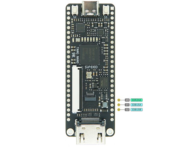
- Pin 49 - the 270 Ω resistor
- Pin 31 - the 33o Ω resistor
- Pin 32 - the 470 Ω resistor
We connect the other end of all the resistors together into a single signal which will be our composite video signal.
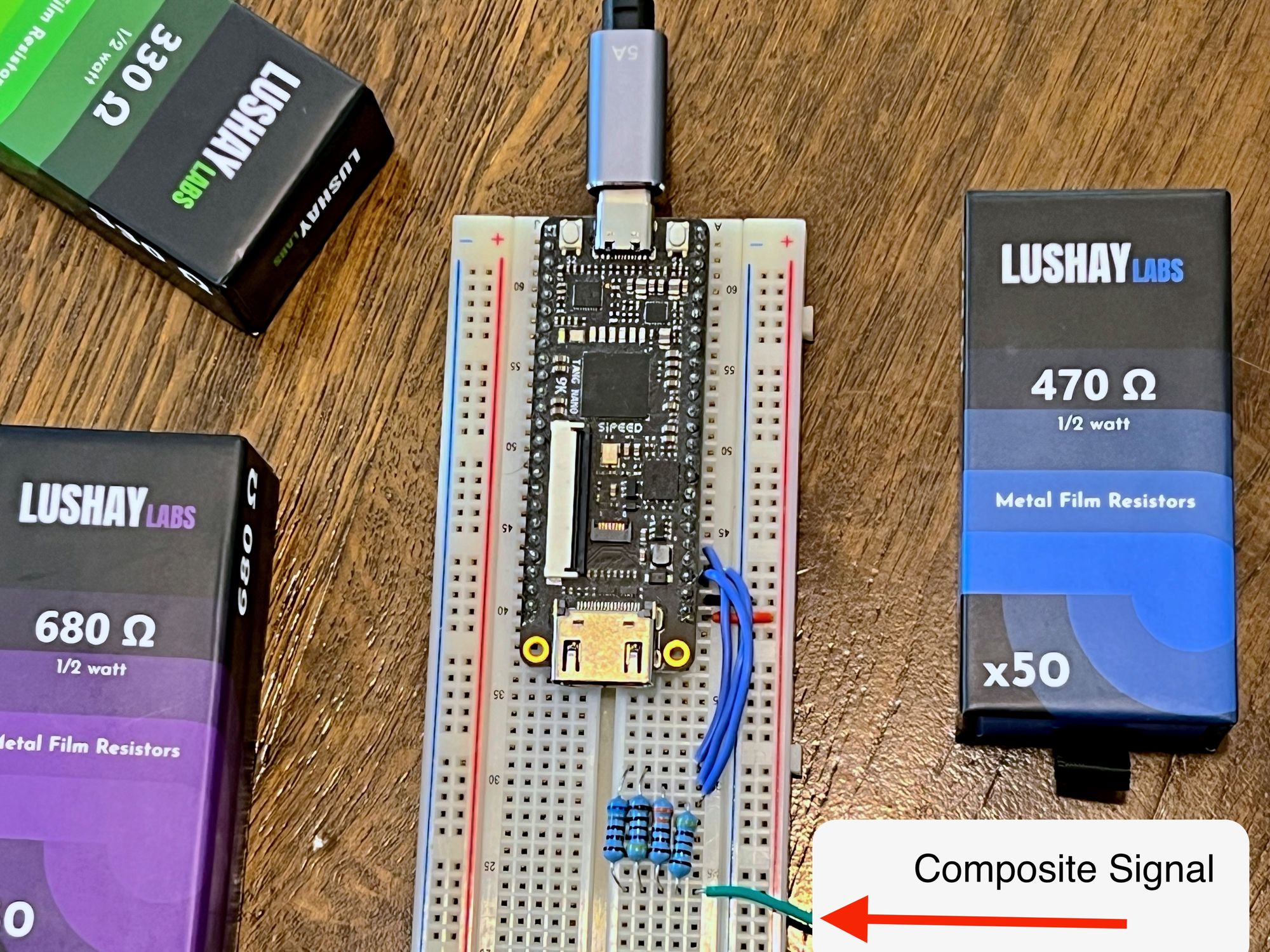
I didn't personally have a 270 Ω resistor but putting what we learned into practice, I can get a pretty convincing 270 Ω resistor by putting a 680Ω and 470Ω resistor in parallel (277 Ω, but close enough for this test).
A composite cable has two wires inside, the composite signal wire which is highlighted above, and a ground wire which can be taken from the next pin on the FPGA.
Implementing a PoC
Before we start drawing full images, I found it extremely helpful to implement a very basic version first, which just shows the minimum requirements for getting something on screen.
The main thing we need to do to get a picture on the screen is to send the correct sync pulses and blanking phases. With those in place, we will have frames being drawn, and then like we saw above it's just a matter of deciding what we want to draw.
Before we get into a more clever and concise solution, let's implement the naive approach in our PoC as I think it makes the logic easy to understand.
Create a file called composite_count_test.v and let's start with a module that will keep track of where we are in the frame:
module composite_count_test (
    input wire clk,
    output reg [9:0] y = 0,
    output wire hsync,
    output wire vsync,
    output wire hblank,
    output wire vblank,
    output wire active_video
);

endmodule
Our module receives our clock and outputs the y position (the scanline number) and a flag for the different sections of each frame.
hsync and vsync will be on when we are in the actual sync pulses (0v), hblank and vblank are for the portions of the sync where the line should be at the blanking voltage and active_video is the area where we should be drawing pixels.
We can add some constants just to help for later (might not use all of them)
  localparam CLOCK_CYCLES_PER_LINE = 12'd1718;
  localparam CLOCK_CYCLES_FOR_HALF_LINE = CLOCK_CYCLES_PER_LINE/2;
  localparam CLOCK_CYCLES_FOR_HSYNC = 12'd128;
  localparam CLOCK_CYCLES_FOR_BACK_PORCH = 12'd120;
  localparam CLOCK_CYCLES_FOR_FRONT_PORCH = 12'd41;
  localparam CLOCK_CYCLES_FOR_VIDEO = CLOCK_CYCLES_PER_LINE - CLOCK_CYCLES_FOR_HSYNC - CLOCK_CYCLES_FOR_BACK_PORCH - CLOCK_CYCLES_FOR_FRONT_PORCH;
  localparam CLOCK_CYCLES_FOR_VSYNC = 12'd738;
  localparam CLOCK_CYCLES_FOR_VSYNC_BLANK = CLOCK_CYCLES_FOR_HALF_LINE - CLOCK_CYCLES_FOR_VSYNC;
```
These aren't exactly in spec with classic NTSC, but close enough to what we need. We are sending 262 scanlines per field, multiplying this by 60 FPS gives us 15,720 scan lines per second which means each scanline takes about 63.61 µs. We have a clock speed of 27Mhz meaning each cycle is about 0.037 µs.
If we take 63.61 and divide it by 0.037 we get 1719 and change, but I would like something even so that each half-scanline is the same length so I went with 1718.
From here we can take each section and either:
- Divide the time by
0.037to get the number of clock cycles - subtract sections to provide the rest of the scanline like in the case of
CLOCK_CYCLES_FOR_VIDEO.
Going back to this image with our frame layout:
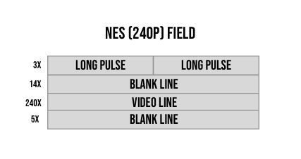
One can say we have 3 types of rows:
- Vertical sync rows (with the long pulses)
- Blanking rows
- Active video rows
By keeping track of our scanline number (y) We can easily determine the type of row:
reg is_vsync_line = 1;
reg is_blanking_line = 0;
reg is_active_line = 0;
reg [11:0] clock_counter = 0;

always @(posedge clk) begin
    clock_counter <= clock_counter + 1;
    if (clock_counter == CLOCK_CYCLES_PER_LINE) begin
        clock_counter <= 0;
        y <= (y == 10'd261) ? 0 : y + 10'd1;
        if (is_vsync_line & y == 2) begin
            is_blanking_line <= 1;
            is_active_line <= 0;
            is_vsync_line <= 0;
        end
        else if (is_blanking_line & y == 16) begin
            is_blanking_line <= 0;
            is_active_line <= 1;
            is_vsync_line <= 0;
        end
        else if (is_active_line & y == 256) begin
            is_blanking_line <= 1;
            is_active_line <= 0;
            is_vsync_line <= 0;
        end
        else if (is_blanking_line & y == 261) begin
            is_blanking_line <= 0;
            is_active_line <= 0;
            is_vsync_line <= 1;
        end
    end
end
The code starts off with only the vertical sync line on since we start our frame from the vertical sync. We then have a standard clock loop where we will increment clock_counter on every rising edge.
We already know the number of clock pulses in a line so we can just count up to CLOCK_CYCLES_PER_LINE and update our y position each cycle.
Besides updating our y we also check based on where we are in the cycle we determine when we need to update our flags, for example, if we are on a blanking line and we just incremented the scanline counter y and its previous value before the increment was 16 then the next line is meant to be an active video line.
We now have all the info needed to set our output flags. To simplify the design, we won't try to exactly decode each part of the frame, instead, we will rely on the following hierarchy:
- Sync flags take top priority
- Blanking flags take second priority
- Active video flags take third priority.
What I mean by this is, that if both vsync and vblank flags are high, then we will set the voltage to 0v as opposed to the blanking's 0.3 as syncs take priority. Again this is only to simplify the decoding slightly.
So let's begin with the two sync flags:
wire first_half = clock_counter < CLOCK_CYCLES_FOR_HALF_LINE;
assign vsync = is_vsync_line & (
    first_half ?
        clock_counter < CLOCK_CYCLES_FOR_VSYNC :
        clock_counter < (CLOCK_CYCLES_FOR_VSYNC + CLOCK_CYCLES_FOR_HALF_LINE)
);
assign hsync = clock_counter < CLOCK_CYCLES_FOR_HSYNC & ~is_vsync_line;
Since on each vertical sync line, we have two pulses, we create a helper wire to track whether we are on the first half of the line or the second half of the line.
clock_counter is counting clock pulses, and we already stored the number of pulses for the actual vsync, since each half of the line starts with the vsync pulse we can just check if the clock_counter is less than the number of pulses.
The horizontal sync is even simpler since it only happens once per line and it happens on both blanking and active video lines.
If we now disregard the sync parts of the pulse (again because of our priority assumption) we can pretty easily calculate the blanking flags:
assign vblank =  ~is_active_line;

localparam START_OF_VIDEO = CLOCK_CYCLES_FOR_HSYNC + CLOCK_CYCLES_FOR_BACK_PORCH;
localparam END_OF_VIDEO = START_OF_VIDEO + CLOCK_CYCLES_FOR_VIDEO;

assign hblank = clock_counter < START_OF_VIDEO | clock_counter >= END_OF_VIDEO;
If you are not on an active video line, then you either have vsync pulses or blanking, since we disregard the pulses we are left with just checking we are not on a video line.
For the horizontal blanking, it is a bit trickier as we have both the back porch and front porch. We create local parameters for storing the start and end pulse of the video and just check if we are between them.
Finally, if we can disregard both syncs and pulses, we only have active video, so we don't even need a flag for it with our assumptions, but we can add something like the following:
assign active_video = is_active_line;With that, we have all the flags needed to create our signal.
Running a Test
To test it we need a constraints file and a top module.
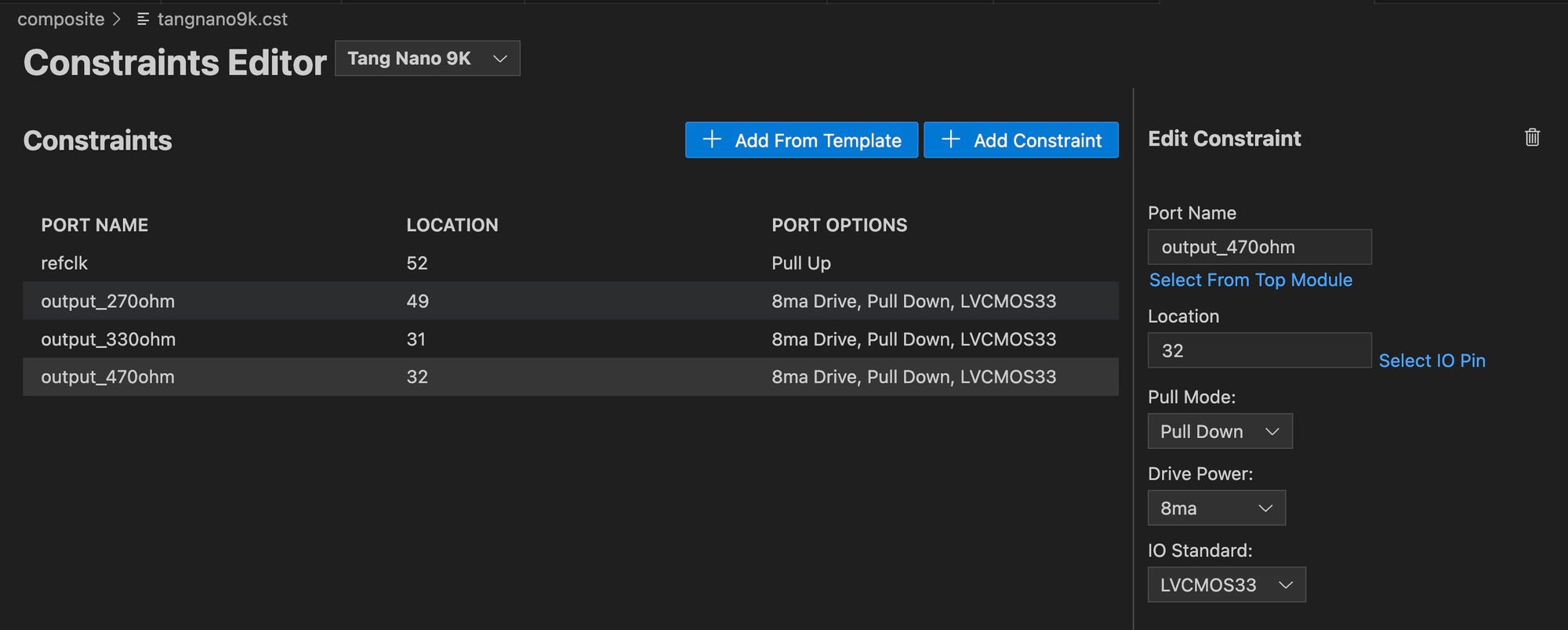
The constraints file is pretty simple as we only have the clock signal and our three resistors. We can create a constraints file as follows:
IO_LOC  "refclk" 52;
IO_PORT "refclk" PULL_MODE=UP;

IO_LOC  "output_270ohm" 49;
IO_PORT "output_270ohm" DRIVE=8 IO_TYPE=LVCMOS33 PULL_MODE=DOWN;

IO_LOC  "output_330ohm" 31;
IO_PORT "output_330ohm" DRIVE=8 IO_TYPE=LVCMOS33 PULL_MODE=DOWN;

IO_LOC  "output_470ohm" 32;
IO_PORT "output_470ohm" DRIVE=8 IO_TYPE=LVCMOS33 PULL_MODE=DOWN;
For the top module we will need to control these resistors using our composite video flags. So in a new file: (top.v)
module top(
    input refclk,
    output reg output_270ohm = 0,
    output reg output_330ohm = 0,
    output reg output_470ohm = 0
);

    wire hsync;
    wire vsync;
    wire hblank;
    wire vblank;
    wire active_video;
    wire [9:0] y;

    composite_count_test cc(
        .clk(refclk),
        .hsync(hsync),
        .vsync(vsync),
        .hblank(hblank),
        .vblank(vblank),
        .active_video(active_video),
        .y(y)
    );

endmodule
We start off with our resistors all at 0v, and just instantiate an instance of our composite counter module.
The last bit is just to respond to the different flags using the priority we defined:
always @(posedge refclk) begin
    if (hsync | vsync) begin
        output_270ohm <= 0;
        output_330ohm <= 0;
        output_470ohm <= 0;
    end
    else if (hblank | vblank) begin
        output_270ohm <= 0;
        output_330ohm <= 0;
        output_470ohm <= 1;
    end
    else if (active_video) begin
        case (y[4:3])
            2'b00: begin
                output_270ohm <= 0;
                output_330ohm <= 0;
                output_470ohm <= 1;
            end
            2'b01: begin
                output_270ohm <= 1;
                output_330ohm <= 0;
                output_470ohm <= 0;
            end
            2'b10: begin
                output_270ohm <= 0;
                output_330ohm <= 1;
                output_470ohm <= 1;
            end
            2'b11: begin
                output_270ohm <= 1;
                output_330ohm <= 1;
                output_470ohm <= 0;
            end
        endcase
    end
end
If any of the sync flags are on we need to set the voltage to 0 and if any of the blank flags are set we need to send 0.3v by connecting only the 470 ohm resistor.
Finally, we have the active video section where we can select any of the 6 voltage options between 0.3-1 we can reach with our resistor network.
Here we will be using just 2 of the bits from our scanline counter to create a repeating pattern of 4 options in increasing brightness. (Just remember you can't set all resistors high as they will exceed 1V and you can't set them all low as it would be considered a sync pulse).
Running this you should get something that looks like the following:
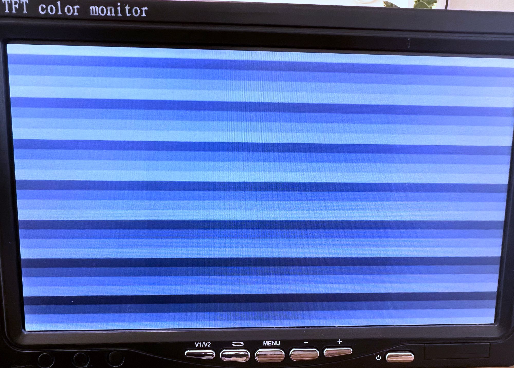
We can easily distinguish our four different shades of gray here, and counting we can see we have about 29+ lines which if we multiply by 8 (since we are reading bits 4 & 5 of the scanline counter) we can see we have pretty much all our 240 visual lines.
The X Direction
The last thing I want to demonstrate is controlling pixels in the horizontal direction. This is already not part of the NTSC standard and is controlled by the speed at which both us and the screen can react to changes.
So we can decide there are 4 pixels in the X direction or 400, and it's arbitrary as the screen expects a constant continuous value.
To demonstrate this let's add a counter to our top module to count in the x direction:
reg [7:0] xCounter = 0;
always @(posedge refclk) begin
    if (hsync)
        xCounter <= 0;
    else
        xCounter <= xCounter + 1;
end
We reset the counter whenever we have a horizontal sync just to keep the frame from scrolling and to have each line aligned, although I do recommend trying with a counter that doesn't reset to see how it will create a scrolling pattern.
Next inside our case statement, instead of the case being on y[4:3] try changing it to case ({y[4], xCounter[6]}). We are still only using two bits to cycle through 4 colors, but we are changing based on the y direction only based on the top bit, which will make our lines twice as high, and now the other bit which controls the color will be based on the 7th bit of our x counter which updates every 64 pulses (2.3µs). If we know that the entire video section is about 1429 clock cycles wide then this is about a 1/23th of the screen's width. For example, if the screen's width is 256 pixels wide then this would mean each square is about 11-12 pixels wide.
Running this updated code should give you a picnic pattern like the following:
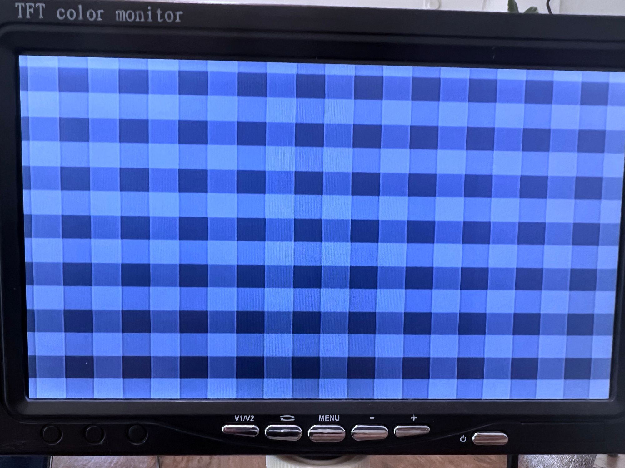
The squares are a bit wider than they are tall since the height is 8 scan lines / ~240 (1/30) and the width is like we saw is closer to 1/23.
With that our PoC is complete and we can move onto creating a project that can draw an image.
Drawing an Image
Drawing an image is not any different that drawing our square pattern above, the only difference is we need to have the image itself stored.
We have 240 vertical lines, and if we use even a modest 256 horizontal columns then we already need to store 61440 pixels which even if we store each pixel as 2-bits using only the 4 colors from before, we would be looking at 15Kb which would be all the shadow ram, adding all 6 colors would be out of the question.
What we need here is to use block ram of which we have almost 60kb, more then enough to store an image. Unfortunately there is not yet support for block ram in the open source toolchain so for this next part you will either need to compile using the official Gowin EDA or you will need to use our cloud synthesis through Lushay Code.
For the rest of this article we will be using the Gowin IDE.
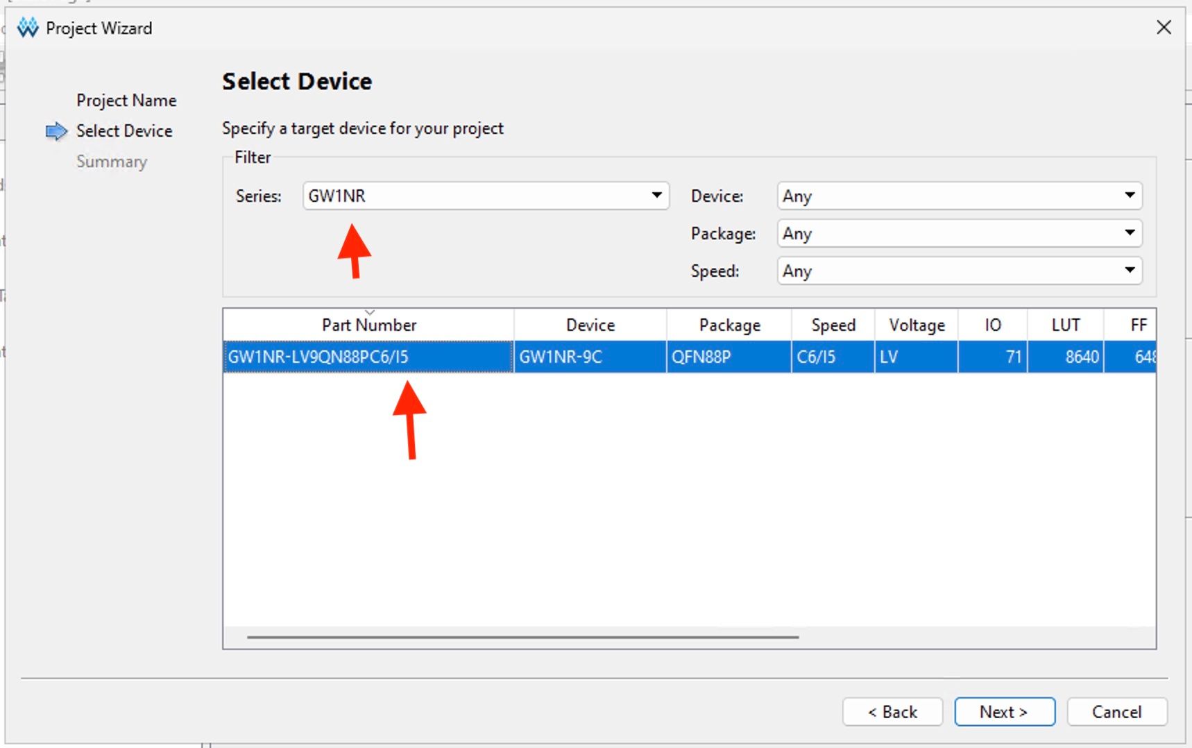
Creating the Project
If you are new to the Gowin EDA, you can start off by creating a new project. From the chip selection select the GW1NR series and then select the device with a part number of GW1NR-LV9QN99PC6/I5:
To add our constraints you can press on the new file button and select "Physical Constraints File" from the list of file types. The contents are the same as before:
IO_LOC  "refclk" 52;
IO_PORT "refclk" PULL_MODE=UP;

IO_LOC  "output_270ohm" 49;
IO_PORT "output_270ohm" DRIVE=8 IO_TYPE=LVCMOS33 PULL_MODE=DOWN;

IO_LOC  "output_330ohm" 31;
IO_PORT "output_330ohm" DRIVE=8 IO_TYPE=LVCMOS33 PULL_MODE=DOWN;

IO_LOC  "output_470ohm" 32;
IO_PORT "output_470ohm" DRIVE=8 IO_TYPE=LVCMOS33 PULL_MODE=DOWN;
Now technically we can just slap in our block RAM leaving everything else the same and call it a day. But Adam went the extra mile and tried to re-create the same timings as an NES.
Simplifying the Timings with PLLs
The NES had a 21.477 Mhz clock and each pixel would be 4 clock cycles, meaning the effective pixel clock rate would be around 5.36. With our 27Mhz clock, it makes it difficult to get to that number. We can clock divide by 5 giving us 5.4 Mhz, but by not being a power of 2 it means we need extra logic for checking and resetting the clock divider.
By having a clock speed we can divide by a power of 2 we can just create a buffer with a fixed number of bits and just let it roll over.
Adam came up with using an 85.5 Mhz clock, dividing this by 16 gives us a 5.34 Mhz pixel clock, which is both more accurate and will allow us to use a power of 2 as our clock divider.
To synthesize this clock speed we will be using an rPLL or Phased Locked Loop to go from 27Mhz to 85.5Mhz.
Just click on "IP Core Generator" from the toolbar or "Tools" menu and then under "Hard Module" > "CLOCK" you should find the rPLL option. Double-clicking on this should open up a wizard for generating a PLL along with a wrapper for convenient usage.
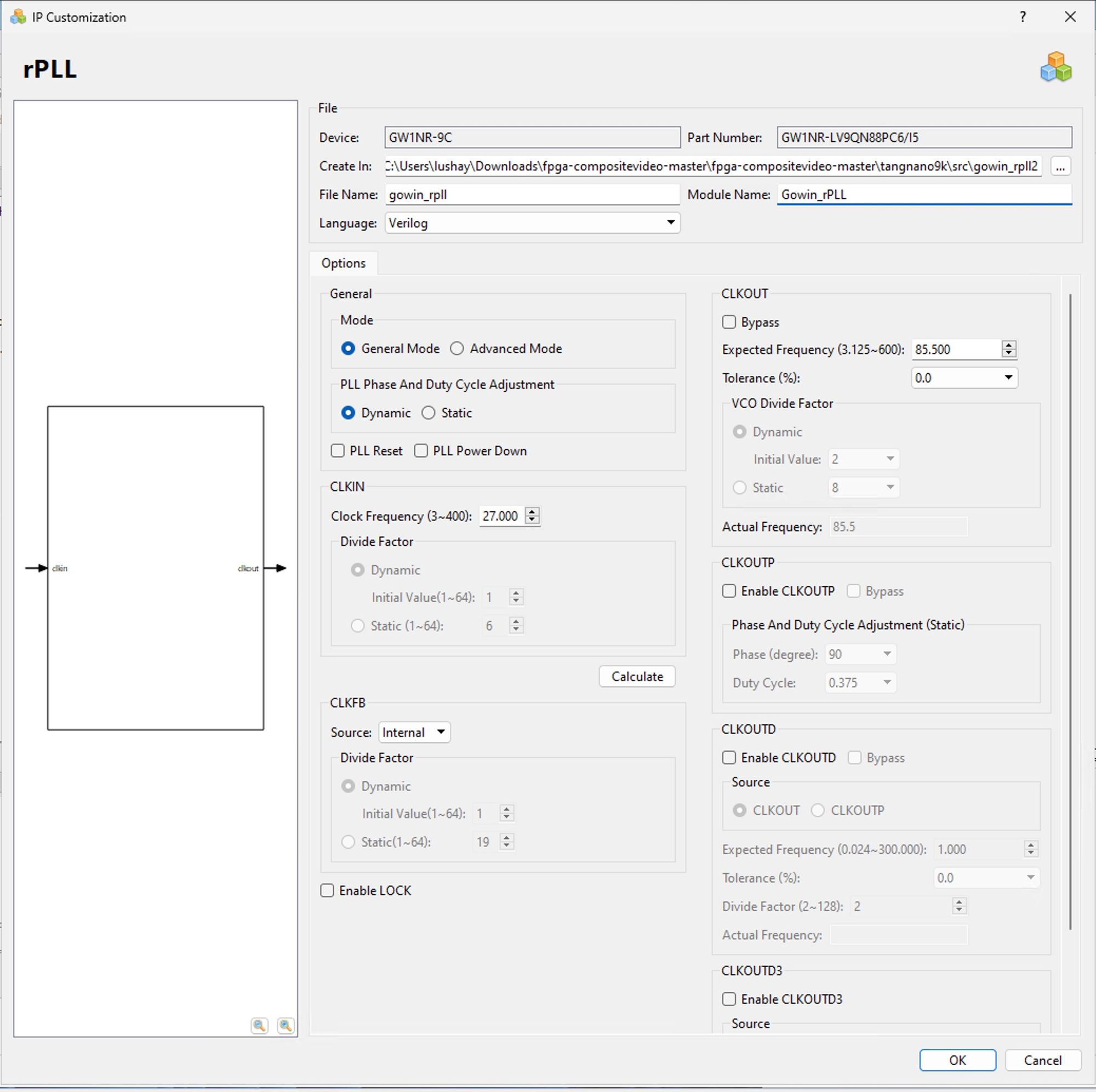
There are a lot of options here as you can do a lot with PLLs, but we don't need most of them right now. For this project, we only need to set the CLKIN frequency to 27Mhz and the CLKOUT to 85.5Mhz. You can then press "Calculate" for it to calculate the closest options.
Clicking OK will create some files and you should accept adding the module to your project. The file contains a module with the following interface:
module Gowin_rPLL(
    output clkout,
    input clkin
);
endmodule
This module basically wraps the many settings of the internal rPLL primitive and simplifies it to a single input where we will send the 27Mhz clock and a single output where we will get our 85.5Mhz clock out.
Putting the Image in BRAM
Next, let's generate a module for the BRAM and we can even pre-load it with the image data. We will be storing each of the 61440 pixels as a 4-bit grayscale value.
The source image is this image from Adam:

and he created this node.js script to convert the image into the desired 4-bit format. You can download the converted file here
With this file, you can go back to the IP Core Generator and this time go under "Memory" > "Block Memory" and find something called SP. This stands for single port memory which means memory that can only handle a single read/write operation at a time (which is perfect for us).
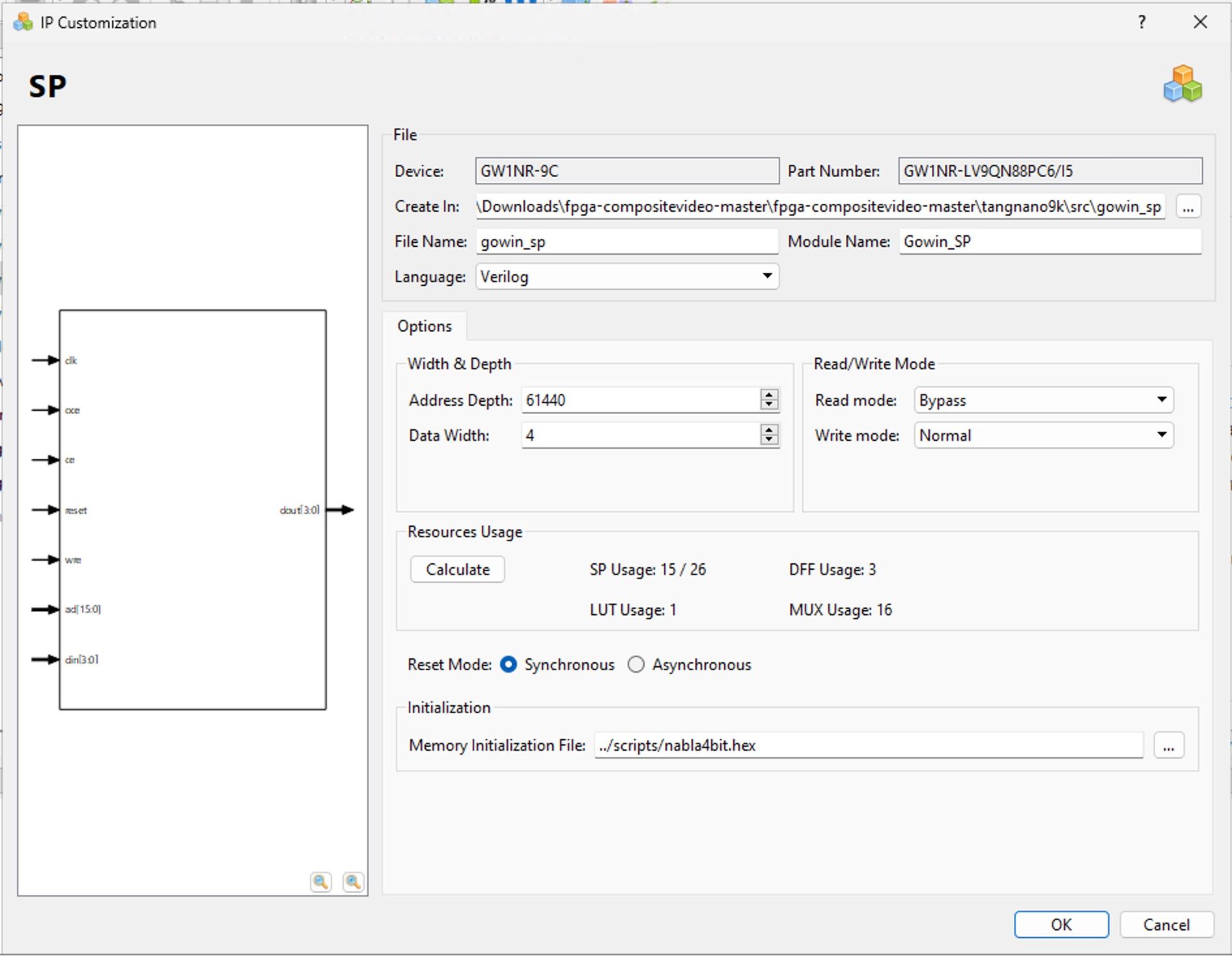
Opening up this generator we only need to change two settings in the first section, the "Address Depth" and "Data Width".
The address depth is essentially how many unique addresses you want, for us 61440 which will give us 1 address per pixel. The second option is the data width, which means how many bits are at each of these addresses, For us we encoded each pixel as 4 bits so we set this to 4.
Finally at the bottom under "Memory Initialization File" select the converted image file from above (or any image encoded in this format) to preload the Bram.
You may have to change the file type in the file browser to "All files" as by default it will only search for special memory initialization files and we will be loading a .hex file.
Updating our Composite Counts
With a new clock speed comes new composite calculations, Luckily by having a clock speed that works well with our pixel time, we can simplify the code.
Create a new Verilog module with the following:
module counts (
    input wire clk,

    output reg [9:0] x = 0,
    output reg [9:0] y = 0,

    output wire hsync,
    output wire vsync,
    output wire hblank,
    output wire vblank
);

endmodule
We have an input for our clk (this time the 85.5Mhz clock) and we have the scanline again as y but this time we also have a variable named x for storing the pixel on the screen in the horizontal direction.
Other than that we have the same flags for our syncs and blanks removing the active_video flag as we saw it is not needed.
Inside we can start with our clock divider, We want to divide by 16 which we can do as follows:
reg [3:0] divider = 0;
wire clk_en = divider == 4'h0;

always @(posedge clk) begin
    divider <= divider + 4'h1;
end
Simple again because 16 is a power of 2. Next, let's start defining some parameters:
localparam DISPLAY_WIDTH = 10'd256;
// Account for overscanned boarders
localparam WIDTH = DISPLAY_WIDTH + 10'd26;
localparam HEIGHT = 10'd240;

localparam VBLANK_LEN = 10'd21;
localparam HBLANK_LEN = 10'd59;

localparam MAX_X = WIDTH + HBLANK_LEN;
localparam MAX_Y = HEIGHT + VBLANK_LEN;
These are all based on the newly divided 5.34 clock.
assign vblank = y >= HEIGHT;
assign hblank = x >= WIDTH;
assign hsync = x >= WIDTH && x < WIDTH + 10'd40;
assign vsync = y == HEIGHT + 10'h5 && x < DISPLAY_WIDTH + 10'd62;
The above code takes advantage of a few things.
- It rearranges the field to start with the video followed by the vsyncs followed by the blanking lines. The flow is all the same, just the reference point for where you start in the repeating signal is less important.
hsyncsare shorter and line up withvsyncsso we don't need to check if we are on a specific line. The handling of anhsyncandvsyncis the same so it doesn't matter if both flags will be on.
By using these two points the code is a lot simpler for these signals. The last things we need to update are the x and y coordinates. For this we can use the following block:
always @(posedge clk) begin : counts
    reg [9:0] next_x;
    reg [9:0] next_y;

    if (clk_en) begin
        next_x = x + 10'b1;
        next_y = y;

        if (next_x == MAX_X) begin
            next_x = 10'h0;
            next_y = y + 10'b1;

            if (next_y == MAX_Y) begin
                next_y = 10'h0;
            end
        end

        x <= next_x;
        y <= next_y;
    end
end
We start by declaring two local registers one for what we want to set the x to and one for what we want to set the y to. Inside we check if we just had a high pulse on our clock divider if so we increment x.
The rest of the block just handles the rollover to a new line when x reaches MAX_X and the rollover to a new line when y reaches MAX_Y.
Connecting it all up
We now have all our modules ready, we just need a top module to tie it all together.
module top (
    input wire refclk,
    output reg output_270ohm = 0,
    output reg output_330ohm = 0,
    output reg output_470ohm = 0
);

endmodule
We start off the same as before, with our reference 27Mhz clock and our 3 resistors. Moving on to the PLL module:
wire clk;
Gowin_rPLL pll (
    .clkin (refclk),
    .clkout(clk)
);
This again wraps the native rPLL primitive using the auto-generated module we created. Next our counts module:
wire hsync;
wire vsync;
wire hblank;
wire vblank;

wire [9:0] x;
wire [9:0] y;

counts counts (
    .clk(clk),

    .x(x),
    .y(y),

    .hsync (hsync),
    .vsync (vsync),
    .hblank(hblank),
    .vblank(vblank)
);
Nothing new here, let's take the x and y coordinates and feed them into our BRAM module:
wire [3:0] pixel;

wire [15:0] address = y * 16'd256 + x;

Gowin_SP ram (
    .clk(clk),
    .ce (1'b1),  // Clock enable
    .oce(1'b1),  // Output clock enable

    .ad  (address),
    .dout(pixel)
);
We are again using the faster 85.5 Mhz clock and we basically just send it a pixel address, which because we aligned the frame to start with the video makes this pretty simple to map. The port ad is the pixel address and the port dout will be the 4 bits we stored in BRAM at that address.
Finally, with our pixels loaded, we can write the main loop which will control our resistors:
always @(posedge clk) begin
    output_270ohm <= 0;
    output_330ohm <= 0;
    output_470ohm <= 0;

    if (pixel >= 4'd12) begin
        // Brightest, 1
        output_270ohm <= 1;
        output_330ohm <= 1;
    end else if (pixel >= 4'd9) begin
        // 0.87
        output_270ohm <= 1;
        output_470ohm <= 1;
    end else if (pixel >= 4'd6) begin
        // 0.76
        output_330ohm <= 1;
        output_470ohm <= 1;
    end else if (pixel >= 4'd4) begin
        // 0.55
        output_270ohm <= 1;
    end else if (pixel >= 4'd2) begin
        // 0.45
        output_330ohm <= 1;
    end else begin
        // Darkest, 0.32
        output_470ohm <= 1;
    end

    if (vblank || hblank) begin
        // Default to black
        output_270ohm <= 0;
        output_330ohm <= 0;
        output_470ohm <= 1;

        if (vsync || hsync) begin
            // Sync level
            output_470ohm <= 0;
        end
    end
end
This code looks at the 4-bit pixel value and maps those 16 values to the 6 brightness values we can create. At the bottom, we have the blanking and sync flags so that they overwrite the video settings.
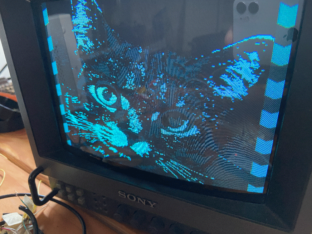
Running this now should give you something like the following:
Conclusions
In this article, we took a look at composite video, the NTSC standard, and how we can implement the 240p variant using the tang nano.
We only got to skim the surface of Adam's project, if you would like to take a deeper dive you can take a look at his repo for this project at the following link. In the repo, you have all the side scripts we talked about as well as a really cool port of this for the Analogue Pocket so definitely worth checking out.
You can also follow him on Twitter here to show support and keep up to date on this project and others.
Extending the Project
If you are looking for ideas on ways you can extend what you learned above to practice these concepts we collected some ideas here:
- Implement more shades of grey - by expanding the resistor network or maybe playing with tri-state outputs.
- Implement interlacing / Implement PAL - explore other composite video frames like 480i or PAL video and create a module implementing them.
- Test Patterns / Video Output - Play with the video generation aspects, maybe implement different patterns or maybe animate a smaller sprite, using a different BRAM layout and drawing code.
- Color (Complex) - We will definitely be covering this in the future, but if you are especially brave you can dive into how color was added to the original black and white standard and try even recreating 1 of the possible colors.
Thank you for reading I hope you enjoyed it, like always if you have any questions or comments feel free to leave them down below in the comments section or DM us on Twitter @LushayLabs.


