
In this article we are going to take a step back from creating modules and instead take a look at how we have been transferring the bitstream to the FPGA to understand the process and protocols involved.
For the Tang Nano itself you probably won't use this information directly since you have everything setup and tools like openFPGALoader, but besides for being interesting, it can come in handy when designing your own boards with an FPGA. Understanding the process will allow you to fully customize and decide how you want to program your own boards / products.
Intro on the Journey
The path from your computer to the FPGA goes through multiple devices and protocols which we will be exploring.
Starting at the lowest level, the FPGA IC itself is designed to be programed via a JTAG interface. JTAG is a standard for externally controlling / reading many devices over a single interface. It is not only used in FPGA programming, but also in testing PCBs, programming microcontrollers, debugging etc.. But in this article we will be focusing on its use here for programming the FPGA.
JTAG itself is the interface protocol, kind of like how SPI might be the physical connection, but then using that communication protocol you have a vendor specific protocol, here defined by Gowin, for programming the bitstream.
JTAG requires 4 physical connections: TDI, TDO, TMS and TCK. TCK is the clock, TMS is used to select the current JTAG state (like function) and TDI and TDO are the data in and out lines.
We will go through it in more detail in a minute, but for now know this is the physical programming interface implemented by the FPGA manufacturer on the IC itself.
From the other side of the spectrum we have the computer, the computer has a bitstream file which is a text file with ASCII ones and zeros which are the bytes to program to the FPGA.
Essentially we need a program for the computer which can take this info and send it to the device using the protocol Gowin designed on-chip over JTAG. For computers - in our day and age - the most practical method of connecting to outside devices is with the USB protocol.
Connecting the USB interface from the computer to the JTAG interface on the FPGA is the FTDI chip, this device can speak both the USB protocol, and by using a sub-protocol called MPSSE you can make it speak JTAG. On-board the Tang Nano 9K there isn't actually an FTDI device (from the FTDI company), but rather a RISC-V chip emulating the FT2232D from FTDI.
The chip on board is the BL702 using the following firmware to emulate the parts of the FT2232D that are required for JTAG programming. MPSSE is the sub-protocol used by the FTDI to convert a series of actions recieved from the computer into the serial protocol JTAG. What I mean by this is from the computer we can just send the FTDI device an MPSSE command saying "send these 4 bytes over TDI and then read back 2 bytes from TDO" and the FTDI would process this command and then perform these actions serially over the 4 JTAG pins (it's a bit more involved then that as we will see below, but that is the gist).
So to recap, we need a program on the computer that can create and send USB packets to the FTDI. The contents of the USB packets need to be the specific MPSSE commands to make the FTDI device send the correct JTAG packets required for programming the FPGA according to the Gowin programming specification.
Quite the protocol inception, but let's take a look at each of these step by step by building our own program to interact with the FPGA over JTAG.
The USB Protocol
The first protocol we can interact with from the computer's end is the USB protocol.
In the USB protocol each device defines a hierarchy of interfaces and endpoints to communicate with. At the lowest level you have endpoints which are unidirectional streams, so either input or output.
A device can have an arbitrary number of endpoints and the reason to have many is it is a convenient way to separate data for different functions on device.
These endpoints are then grouped into interfaces, an interface is another logical separation for these endpoints. In our use-case the FTDI chip is doing two things, it is used for the JTAG communication but it is also used as a UART serial port to the tang nano.
So the FTDI has two separate interfaces one for JTAG and one for UART and then each of these interfaces has two endpoints one for input and one for output. But unless you are trying to follow a specific sub-specification you can define the interfaces and endpoints however you like.
Besides for the endpoints defined by the device, there is also a special endpoint 0 also known as the "control endpoint" which unlike the other endpoints is a bidirectional endpoint used for things like sending commands or reading configuration.
Let's start off by creating a basic USB application so that we can learn some of the concepts along the way.
WebUSB first Steps
In this article we will be using the relatively new WebUSB javascript specification to communicate with the USB device directly from the browser, mainly because it is cross-platform and supported by Chrome, Edge and Opera and so if your browser is up to date you won't need to download anything.
Some Setup
To get started create a new file called index.html with the following contents:
<!DOCTYPE html>
<html>
    <head>
        <title>WebUSB</title>
    </head>
    <body>
        <h1>WebUSB Tests</h1>
        <button id="connectBtn">Connect</button>
        <p>Device Connected: <span id="deviceConnected">None</span></p>
        <button id="descriptorsBtn">Get Device Info</button>
        <section id="deviceInfo"></section>
        <script>
            // add code here
        </script>
    </body>
</html>
It's ok if you don't know anything about HTML, just know that a blank webpage looks like the following:
<!DOCTYPE html>
<html>
    <head>
        <title>Page Title</title>
    </head>
    <body>

    </body>
</html>
So what we are adding to this web page is first of all a title using the h1 or Heading 1 tag with the text "WebUSB Tests". In HTML you have 6 levels of headers from h1 to h6 where h1 is meant to be the largest header and h6 the smallest.
Next we have a button with the text "Connect" which we will use to start the USB device pairing, this is then followed by a p tag which is a paragraph tag which is a general purpose tag for displaying text.
We are using this paragraph tag to display whether or not we have already connected and paired a USB device to the browser.
We wrap the word "None" with a span and give it an id so that we can reference it later and update the text. A span is by default a non visual element, meaning it doesn't affect the looks or layout which is useful for wrapping dynamic areas of your page for updating later.
Next we have another button to get the device info once we have a paired device followed by an empty section right after the button which is a placeholder where we will add the device info we read.
The last tag is a script tag where we can add JavaScript code for interacting with the page and use JavaScript APIs like WebUSB.
You can also optionally add CSS to style the page, for example you can add the following after the title in the head tag to style the page a bit:
<style>
* {
    font-family: 'Segoe UI', Tahoma, Geneva, Verdana, sans-serif;
}
#deviceConnected {
    background: rgb(13, 98, 255);
    color: #FFF;
    padding: 4px 8px;
    border-radius: 4px;
    font-size: 12px;
    text-transform: uppercase;
    font-weight: bold;
}
#deviceInfo {
    margin-top: 16px;
    border: 1px solid #CCC;
    padding: 8px;
    border-radius: 4px;
    width: fit-content;
    min-width: 300px;
    padding: 5px 10px;
    font-size: 13px;
}
#deviceInfo * {
    margin: 0;
    color: #444;
    margin: 6px 0;
}
#deviceInfo span {
    color: #000;
    font-weight: bold;
}
</style>
This is of-course optional and simply updates the design of what we will be doing so I won't get into the specific CSS used here. I will say that the # sign is used with an id to match a tag with that id, and a tag name without a # is used to match against that same tag.
Also a space in the tag represents nesting, for example #deviceInfo span will target any span tag inside an outer element that has the id deviceInfo. It doesn't have to be immediately inside and could be nested a few levels deep, but any span with a parent element with the deviceInfo id somewhere up the chain will have the text color black and be bold in this case.
Opening the page in your browser (by for example double clicking on the file) should give you something like the following:
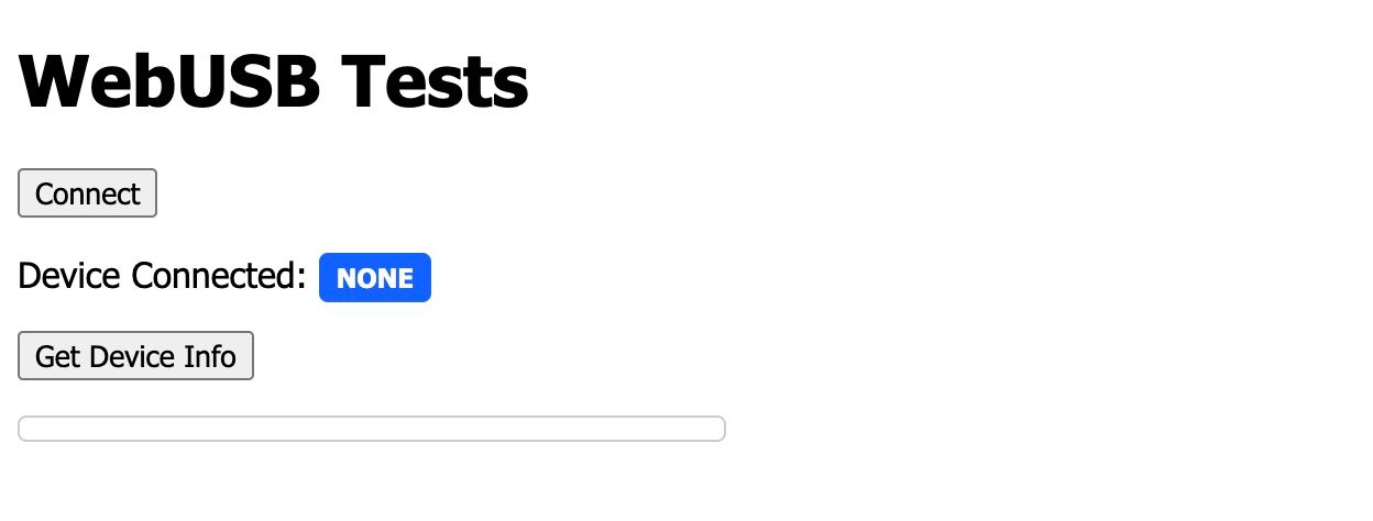
We now have everything we need to start using the WebUSB apis.
Pairing the Device
To get started let's pair a USB device to the browser, in-between the opening and closing script tags let's start adding some JavaScript:
const connectBtn = document.getElementById('connectBtn');
const descriptorsBtn = document.getElementById('descriptorsBtn');
const deviceConnected = document.getElementById('deviceConnected');
const deviceInfo = document.getElementById('deviceInfo');
We start with four constants, this code just gets references to the four elements we put IDs on, so we have a reference to each of the two buttons, another reference for the "connected status" so we can update the text and another reference to the box for the device info so we can fill it in programmatically.
let device = null;
function setDevice(newDevice) {
    if (newDevice) {
        device = newDevice;
        deviceConnected.innerText = 'Yes';
    } else {
        device = null;
        deviceConnected.innerText = 'None';
    }
}
Next we can have a global variable to store the currently selected device, we initialize the value to null which is like an empty value, representing no device connected in our case.
We then define a function for updating whether or not we have a device. This function accepts a parameter, and based on whether the parameter is a new device or null, we both set this device variable and update the text of the connected tag accordingly.
The last thing we need to do, to pair a device is call the WebUSB api whenever someone presses the first button:
connectBtn.addEventListener('click', async () => {
    const newDevice = await navigator.usb.requestDevice({ filters: [] });
    setDevice(newDevice);
});
Here we add a new "event listener" or event handler, whenever the click event is triggered (which happens automatically whenever the button is clicked via the browser) we attach a function which will run.
Inside the function we simply call the requestDevice function which will prompt the user to pair a device. You can see the function receives an object with a filters property. This can be used to only show the user devices with a certain vendor id and/or product id, for example we can put the ids for the Tang Nano and only it will show up in the prompt to the user. For now I will leave it blank so you will see all USB devices.
If you now refresh the page and click on the first button, you should see something like the following:
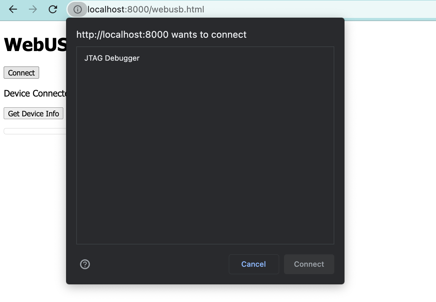
Assuming your Tang Nano is plugged in you can select it from the list and press connect. Once doing so you should see the status update to connected.
Now refreshing the page "disconnects" the device, but not really, we lose our reference to the device since the page refreshed, but we still have permission to the device. So to make it so that we re-get the reference whenever the page is refreshed we can add the following:
document.addEventListener('DOMContentLoaded', async () => {
    const devices = await navigator.usb.getDevices();
    if (devices.length > 0) {
        setDevice(devices[0]);
    }
});
Here we are saying, once the page loads, get all connected devices. We are using the getDevices function from the WebUSB api for this. If we have a paired device we will use our same function as before to set the device to the first device returned.
Now refreshing the page you should see the status stay as connected.
Inspecting the Device
We have a few ways of debugging things in JavaScript in the context of a browser. First of all you can use the console.log function to print anything out to the console. For example console.log(device) after setting it (e.g. inside setDevice) will print out the device for you to inspect.
Another option is the inline-debugger which you can trigger simply by adding the word debugger; wherever you want in the code. This will cause the browser to stop execution at that point and allow you to step line-by-line inspecting the values of variables in that scope.
What we will do is simply access the variable manually since it is a global top-level variable. To do this open up the developer tools on the page and find the console tab.
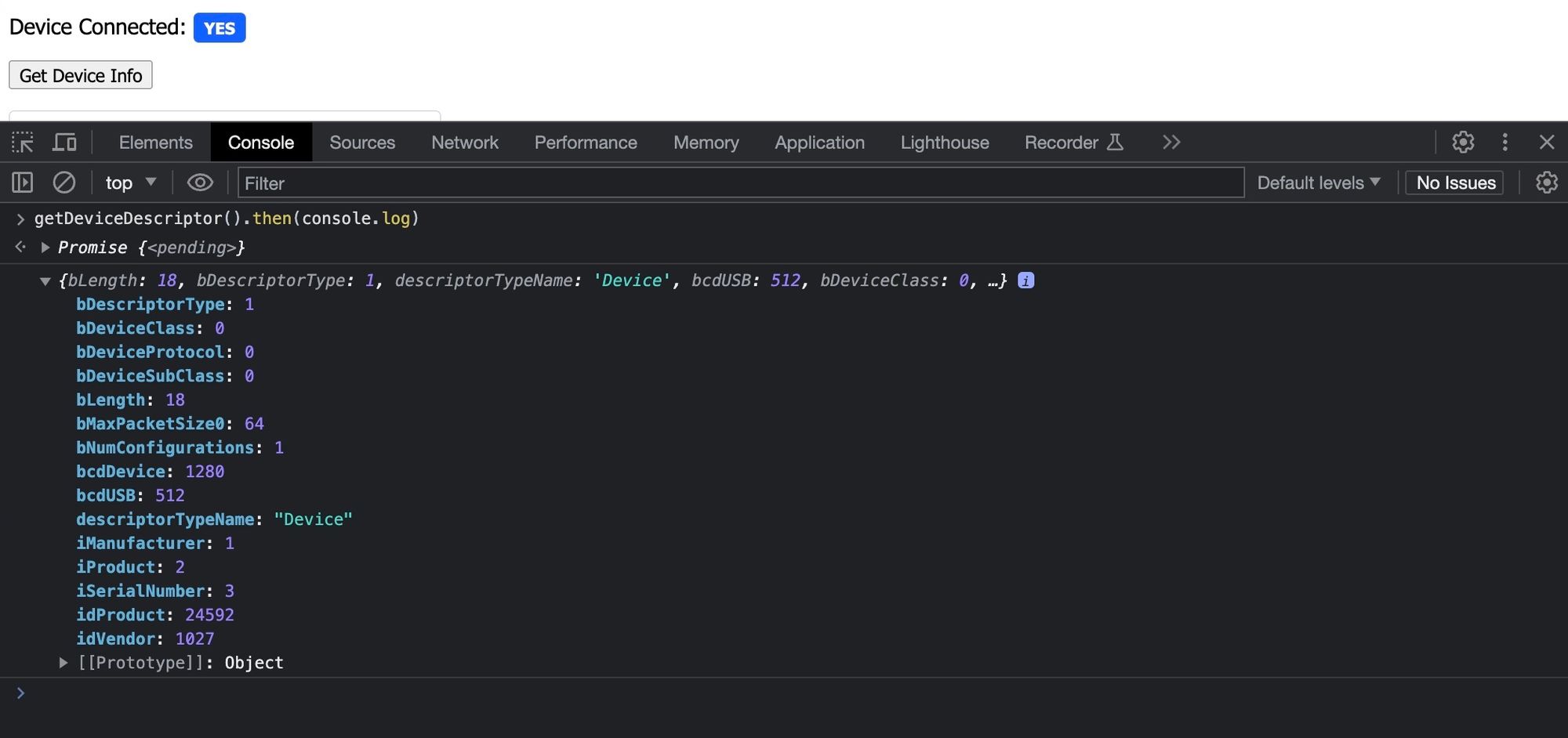
Inside this tab you have an interactive JavaScript interpreter so you can simply type the name of the global variable, in our case device and press enter to get something like the following:
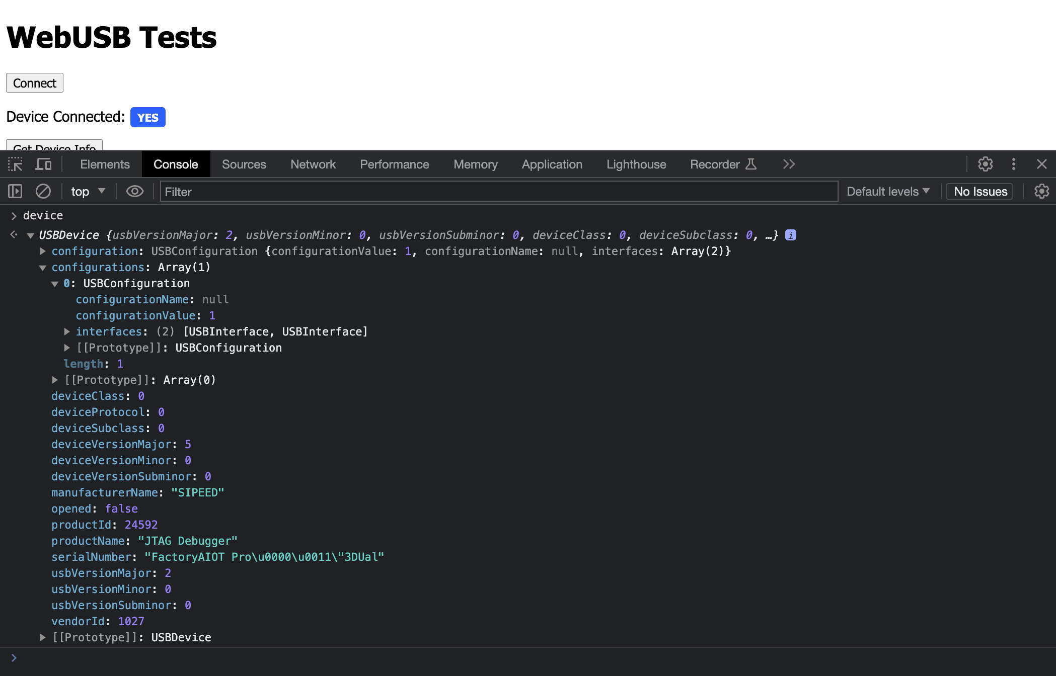
Some interesting things to see here are things like the manufacturer and product names. You also have a serial number, the product and vendor IDs and a configurations object. This relates to what we discussed earlier, where a device has multiple interfaces and each interface is made up of endpoints which are unidirectional streams.
On the Tang Nano we have 2 interfaces each of which having 2 endpoints, the first interface is the JTAG interface for programing the bitstream and the other interface is for the serial UART connection to the FPGA.
But before we start displaying this info on screen let's take a detour to understand how JavaScript got this information through the USB protocol, and we will do this by getting the information ourselves.
USB Descriptors
USB devices contain different types of descriptors containing information "describing" the device. For example you have device descriptors which contain general information about the device, configuration descriptors which as displayed above contain info about the different interfaces and endpoints among others.
In the usb protocol we have special transfers which are called "control transfers" which use the special bi-directional endpoint 0. We will use this to request a specific descriptor and then we will decode the bytes returned to extract the information we need.
Let's create the first function which will allow us to get a descriptor:
async function getDescriptor(
    descriptorType,
    descriptorIndex,
    descriptorLength
) {
    if (!device) { return; }
    await device.open();
    const res = await device.controlTransferIn({
        requestType: 'standard',
        recipient: 'device',
        request: 0x06,
        value: descriptorType,
        index: descriptorIndex,
        length: descriptorLength
    }, descriptorLength);
    const responseBytes = new Uint8Array(res.data.buffer);
    await device.close();
    return responseBytes;
}
This function receives as parameters the type of descriptor we want, the index of the descriptor (for when there are multiple of the same type) and the length or number of bytes to read back from the usb device.
We then start the function off with a guard clause to make sure we connected a device already, if not we will just return doing nothing. Next we open the device so that we can interact with it, this claims the device and no other programs will be able to use it until we close the device. We could have just opened the device once at the beginning of the program and only close it at the end, but again this would lock the device from other programs and if we would forgot / not release the device because of an error we would have to disconnect and replug-in the device to release it. So to be safer we will just open and close the device whenever we need it.
In between the open and close we have the main function controlTransferIn which will send the control command. This - along with controlTransferOut - are used for all control commands not just getting descriptors, it receives an object containing the request type which can be things like standard for standard commands, class for class-specific commands or vendor for vendor specific commands. Next we have the packet recipient, this can be things like device for the device itself, interface for a specific interface or endpoint for a specific endpoint.
The third option here is request which you can think of as a sub-request-type, here we are sending the GET_DESCRIPTOR sub-request-type which is 0x06 in hex. Now the next three parameters of value, index and length are used differently per use-case, here value is used to represent the descriptor type we are trying to retrieve, index is the descriptor offset for retrieving the next descriptor of the same type and length is used to say how many bytes we would like returned to us.
After passing the object we also pass another parameter which is again the length, this is not part of the USB protocol but rather a parameter for the javascript WebUSB library to know how many bytes to read after sending the command.
We get back a results object which we called res and I have found it is not that easy to work with the raw bytes in this form, so we convert the results into a Uint8Array which is an array of unsigned 8 bit integers which works out to exactly represent bytes.
The function simply returns this new byte array as the results from our function.
Now the next thing we need is the ability to retrieve strings stored on the USB device. Because the standard descriptors have a fixed length, things like strings for manufacturer name or device name are stored as an index and then the actual string is stored as a separate descriptor called a string descriptor.
async function getStringFromStringDescriptor(stringDescriptorIndex) {
    if (stringDescriptorIndex === 0) { return ''; }
    const descriptorBytes = await getDescriptor(
        0x0300 | stringDescriptorIndex,
        0x0409,
        255
    );
    if (!descriptorBytes) { return ''; }
    let decodedString = '';
    for (let i = 2; i < descriptorBytes.length; i += 2) {
        const charCode = descriptorBytes[i] | (descriptorBytes[i + 1] << 8);
        if (charCode === 0) { break; }
        decodedString += String.fromCharCode(charCode);
    }
    return decodedString;
}
This function receives the string index which is what will be stored instead of the string in the other descriptors. These indices start from 1 not 0, so if 0 is stored as the string descriptor index it means their is no string so we return a blank string.
We then use are previous function to retrieve the string descriptor. The way this works is the descriptor type needs to be 0x0300 plus the index, so the first descriptor will be request type 0x0301 and the second will be 0x0302 etc.. Since the indices for the descriptors don't overlap the upper byte containing the 0x03 which can just bit-wise OR the two numbers together to get the result.
It's interesting that the index wasn't used for offsetting the string descriptors, but instead the second parameter descriptorIndex is used to set which language we want to get returned. So a device can store each of the strings in multiple languages and then based on the host return the correct variation.
We will be using 0x0409 which is the language code for US-english, but you can take a look at locale codes like on this list here to get an idea of what the other theoretical values would be.
Finally the third parameter is the length and since we don't know in advance we will send 255 just to be safe (even though the mock-ftdi chip we are using only has a max buffer of 64 so we could have used that as well).
The first byte of the descriptor is the length of the total descriptor (not just the length of the string) and the next byte is the descriptor type, which since we are dealing with string descriptors will always be 0x03. Here are some of the other types just for reference:
| Number | Type |
|---|---|
| 0x01 | Device Descriptor |
| 0x02 | Configuration Descriptor |
| 0x03 | String Descriptor |
| 0x04 | Interface Descriptor |
| 0x05 | Endpoint Descriptor |
After the length and type of the descriptor, the rest of the bytes are the actual bytes of the string, here each character is stored as 2 bytes with the first being the least significant byte and the second being the upper byte. So we simply have a for-loop starting from the 3rd byte (index 2) again since the first two are not related to the string, and we increment each time by 2 bytes.
Inside the for-loop we shift the upper byte to the left 8 bits and bit-wise OR it with the lower byte to get the combined byte. If this character is the null character or 0x00 character we will end the string, this is optional, and I noticed that on the Sipeed device there are some characters after the null terminator but I will leave them off.
The final line in the for-loop concatenates the next character to the string containing all the previous characters by converting the byte we calculated to a string.
With these two helper functions done we can create a function to get the actual device descriptor and parse it's bytes:
const DESCRIPTOR_TYPE_NAMES = {
    0x01: 'Device',
    0x02: 'Configuration',
    0x03: 'String',
    0x04: 'Interface',
    0x05: 'Endpoint'
}

async function getDeviceDescriptor() {
    const bytes = await getDescriptor(0x0100, 0x00, 0x12);
    return {
        bLength: bytes[0],
        bDescriptorType: bytes[1],
        descriptorTypeName: DESCRIPTOR_TYPE_NAMES[bytes[1]],
        bcdUSB: bytes[2] + (bytes[3] << 8),
        bDeviceClass: bytes[4],
        bDeviceSubClass: bytes[5],
        bDeviceProtocol: bytes[6],
        bMaxPacketSize0: bytes[7],
        idVendor: bytes[8] + (bytes[9] << 8),
        idProduct: bytes[10] + (bytes[11] << 8),
        bcdDevice: bytes[12] + (bytes[13] << 8),
        iManufacturer: bytes[14],
        iProduct: bytes[15],
        iSerialNumber: bytes[16],
        bNumConfigurations: bytes[17]
    }
}
We start by getting the device descriptor's bytes for which we need to send descriptor type 0x0100, descriptor index 0x00 and the length of this descriptor is 0x12 or 18 bytes.
I won't go into each of the decoded fields, but what I will say is all the fields that start with a lowercase i are indices to string descriptors, so we could send these values to our other function to get the actual strings for these which we will do soon.
To test out what we did so-far you can go back to the console and type in the following: getDeviceDescriptor().then(console.log). Since we are dealing with asynchronous functions, which are processes that happen in the background, we won't immediately get the response back, instead we get an object called a promise that like the name implies is a sort of "promise" that you will get an answer in the future. You can use the then method on the promise object passing in a function for what to do when the result is ready. We have been using the await keyword when calling these functions which is a special keyword telling JavaScript to pause your function and move it to the background until the function you called is ready abstracting this away most of the time.
Here we will just use the then method passing it the console.log function which will simply print the results to the console.
We can then take the value of one of the string indices for example iManufacturer and use our other function to retrieve the string value for this. So type in the console the following: getStringFromStringDescriptor(1).then(console.log)
and this time you should see it print the manufacturer name like so:

With this working let's go back and create one more function to get the configuration descriptors:
async function getConfigurationDescriptor() {
    let bytes = await getDescriptor(0x0200, 0x00, 0x09);
    const length = bytes[2] + (bytes[3] << 8)
    bytes = await getDescriptor(0x0200, 0x00, length);

    const interfaceDescriptors = [];
    let lastInterface = null

    for (let i = 9; i < bytes.length; ) {
        const descriptorLength = bytes[i];
        const descriptor = bytes.slice(i, i + descriptorLength);
        const descriptorType = descriptor[1];
        const descriptorTypeName = DESCRIPTOR_TYPE_NAMES[descriptorType];

        if (descriptorTypeName === 'Interface') {
            const interfaceDescriptor = {
                bLength: descriptor[0],
                bDescriptorType: descriptor[1],
                bInterfaceNumber: descriptor[2],
                bAlternateSetting: descriptor[3],
                bNumEndpoints: descriptor[4],
                bInterfaceClass: descriptor[5],
                bInterfaceSubClass: descriptor[6],
                bInterfaceProtocol: descriptor[7],
                iInterface: descriptor[8],
                interfaceName: await getStringFromStringDescriptor(descriptor[8]),
                endpoints: []
            }
            interfaceDescriptors.push(interfaceDescriptor);
            lastInterface = interfaceDescriptor;
        } else if (descriptorTypeName === 'Endpoint') {
            const endpointDescriptor = {
                bLength: descriptor[0],
                bDescriptorType: descriptor[1],
                bEndpointAddress: descriptor[2],
                bmAttributes: descriptor[3],
                wMaxPacketSize: descriptor[4] + (descriptor[5] << 8),
                bInterval: descriptor[6]
            }
            lastInterface.endpoints.push(endpointDescriptor);
        }

        i += descriptorLength;
    }

    return {
        bLength: bytes[0],
        bDescriptorType: bytes[1],
        descriptorTypeName: DESCRIPTOR_TYPE_NAMES[bytes[1]],
        wTotalLength: length,
        bNumInterfaces: bytes[4],
        bConfigurationValue: bytes[5],
        iConfiguration: bytes[6],
        bmAttributes: bytes[7],
        bMaxPower: bytes[8],
        interfaceDescriptors
    }
}
I won't go through this function line-by-line, since it is just more of the same. There are a few things that are worth mentioning though. The configuration descriptor itself is 9 bytes long, but in-order to get the interface and endpoint descriptors you have to request the configuration descriptor and set the number of bytes to return to the number of bytes for the configuration descriptor and all the interfaces and endpoints included within.
The problem is the number of bytes required for this is stored inside the configuration descriptor itself. So to get around this we first read the configuration descriptor on it's own (just the first 9 bytes) we extract from it the 3rd and 4th bytes (index 2 and 3) as they contain the total length of bytes to get all the descriptors we want and then we re-read the configuration descriptor passing in the new length.
The structure of the bytes returned are as follows:
- Configuration Descriptor
- - Interface 1
- - - Enpoint 1 of interface 1
- - - Endpoint 2 of interface 1
- - Interface 2
- - - Endpoint 1 of interface 2
- - - Endpoint 2 of interface 2
and so on essentially in a depth-first tree structure. So the rest of the function is essentially just going one descriptor starting at byte 10 (after the first 9 bytes of the configuration descriptor) checking what the length of the next sub-descriptor is and then we slice that part off as its own separate array of bytes so that we can parse it separately.
Using the knowledge of how the bytes are ordered, we know that if the type of the sub descriptor is an endpoint descriptor, we can know that it belongs to the previous interface descriptor.
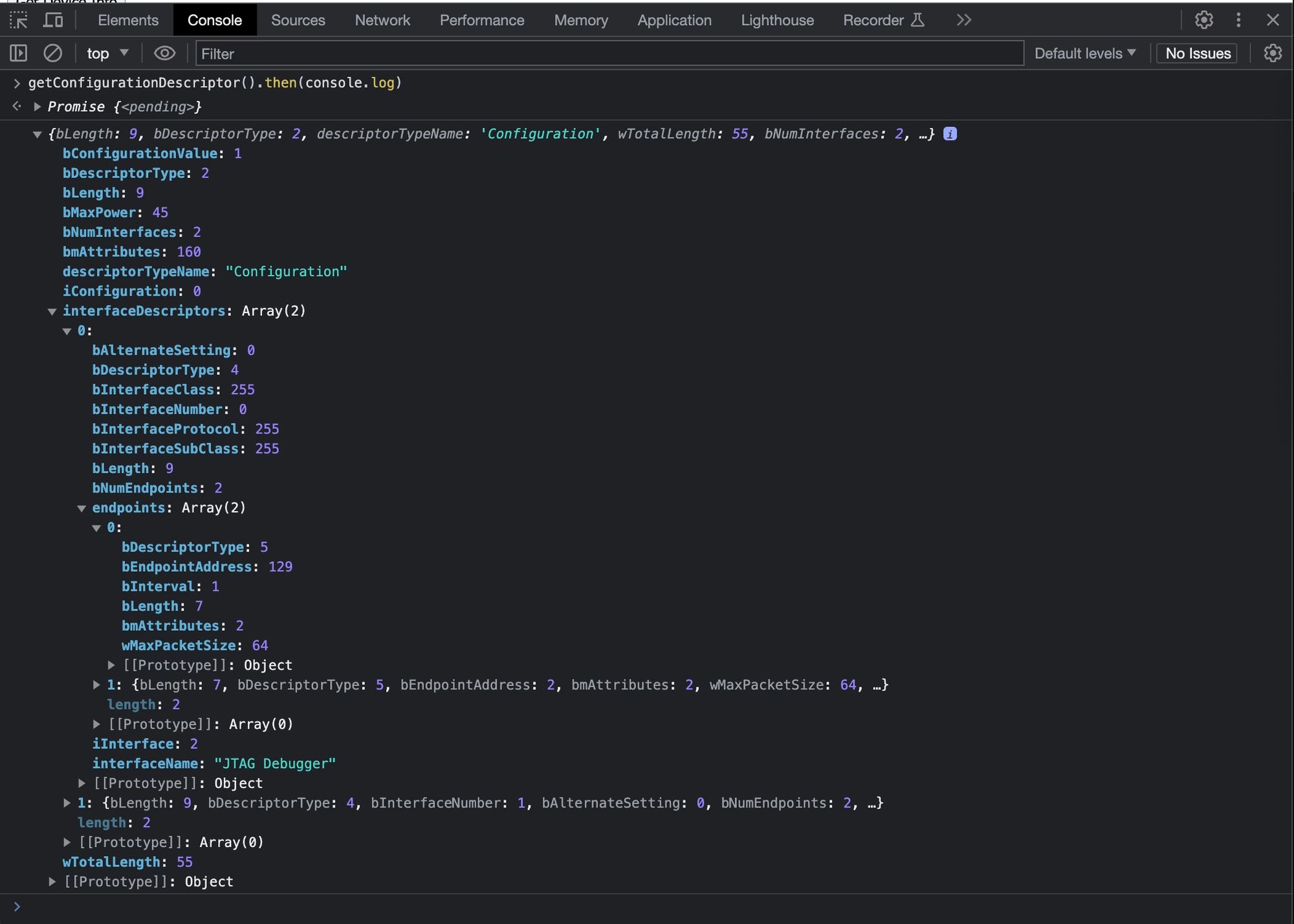
We can test this function as well from the javascript console (first refreshing the page for the changes to take effect): getConfigurationDescriptor().then(console.log)
Giving us:
Displaying the Data
Last but not least, let's get this data on screen by attaching everything we did to the second on-screen button:
function htmlList(parent) {
    const list = document.createElement('ul');
    list.addRow = (label) => {
        const row = document.createElement('li');
        row.innerHTML = label;
        list.appendChild(row);
        return row;
    }
    parent.appendChild(list);
    return list;
}

descriptorsBtn.addEventListener('click', async () => {
    if (!device) { return; }

    const deviceDescriptor = await getDeviceDescriptor();
    const manufacturerName = await getStringFromStringDescriptor(deviceDescriptor.iManufacturer);
    const productName = await getStringFromStringDescriptor(deviceDescriptor.iProduct);
    const serialNumber = await getStringFromStringDescriptor(deviceDescriptor.iSerialNumber);

    const vendorId = deviceDescriptor.idVendor.toString(16).padStart(4, '0');
    const productId = deviceDescriptor.idProduct.toString(16).padStart(4, '0');

    const configurationDescriptor = await getConfigurationDescriptor();

    deviceInfo.innerHTML = ''
    deviceInfo.addText = (key, val) => {
        const p = document.createElement('p');
        const label = document.createElement('span');
        label.innerText = key + ': ';
        p.appendChild(label);
        p.appendChild(document.createTextNode(val));
        deviceInfo.appendChild(p);
    }

    deviceInfo.addText('Manufacturer Name', manufacturerName);
    deviceInfo.addText('Product Name', productName);
    deviceInfo.addText('Serial Number', serialNumber);
    deviceInfo.addText('Number of Interfaces', configurationDescriptor.bNumInterfaces);
    deviceInfo.addText('Vendor ID', `0x${vendorId}`);
    deviceInfo.addText('Product ID', `0x${productId}`);
    deviceInfo.addText('Interface Tree', '');

    const interfaceTree = htmlList(deviceInfo);

    for (const interfaceDescriptor of configurationDescriptor.interfaceDescriptors) {
        const interfaceTitle = `Interface ${interfaceDescriptor.bInterfaceNumber}: ${interfaceDescriptor.interfaceName}`;
        const interfaceRow = interfaceTree.addRow(interfaceTitle);

        const endpointTree = htmlList(interfaceRow);

        for (const endpointDescriptor of interfaceDescriptor.endpoints) {
            const endpointTitle = `Endpoint ${endpointDescriptor.bEndpointAddress & 0x0F}:`;
            const endpointItem = endpointTree.addRow(endpointTitle);

            const endpointInfo = htmlList(endpointItem);
            const endpointDirection = endpointDescriptor.bEndpointAddress & 0x80 ? 'In' : 'Out';
            endpointInfo.addRow(`Direction: ${endpointDirection}`);
            endpointInfo.addRow(`Max Packet Size ${endpointDescriptor.wMaxPacketSize}`);
        }
    }
});
The first function is just a helper function to create a new ul HTML element which stands for an unordered-list, and on this list we add a helper function for easily adding lis which are line-items.
Next we connect a handler for the click event of our second button. This handler can be split into two parts, the first handles getting all the descriptors along with the strings for a bunch of the properties and the second half is what creates the HTML to display on screen.
Nothing too interesting to add here, except maybe the part about interpreting bEndpointAddress on the endpoints. Here the bottom four bits represent the endpoint number and the upper four bits represent the direction, a value of 1 for the top bits means it's an input endpoint and a value of 0 means it's an output.
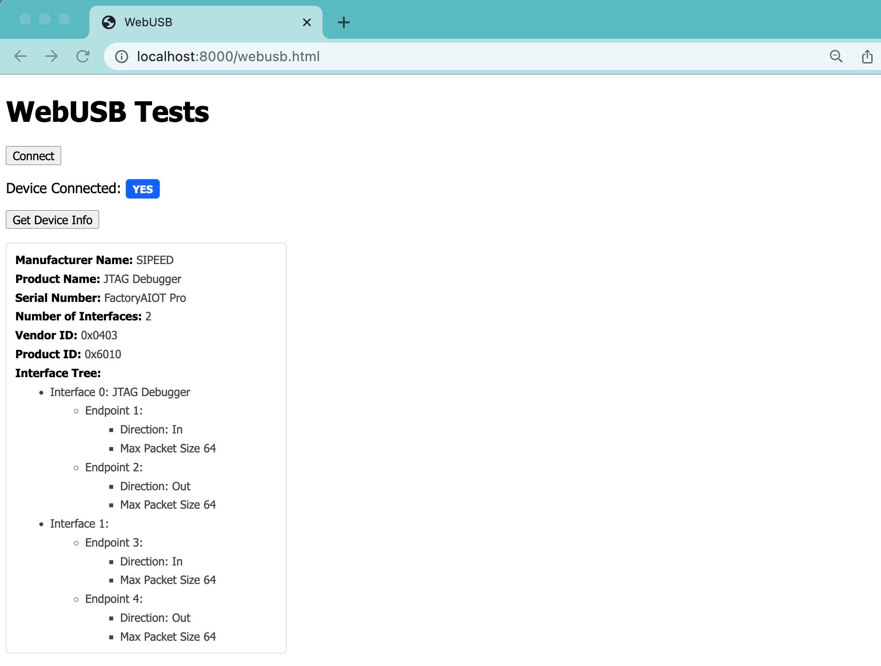
Other then that we should be done here. Refreshing the page and clicking on the button should give you something like the following:
With that we finished our detour, hopefully learning a bit about the USB protocol and about using the WebUSB API. Let's move onto looking at the MPSSE protocol next.
FTDI & MPSSE
With a usb device ready, we can now send packets to the device using an endpoint on one of the interfaces, but to understand what we need to send we need to take a look at the FTDI protocol.
The FTDI commands we will be using are a sub-protocol called MPSSE which stands for Multi-Protocol synchronous serial engine, and it is basically a generic interface that can be used to implement multiple serial protocols JTAG being one of them.
As you can see from this PDF the FTDI IC itself can be connected up to 16 I/Os and you are able to control these using different FTDI commands:
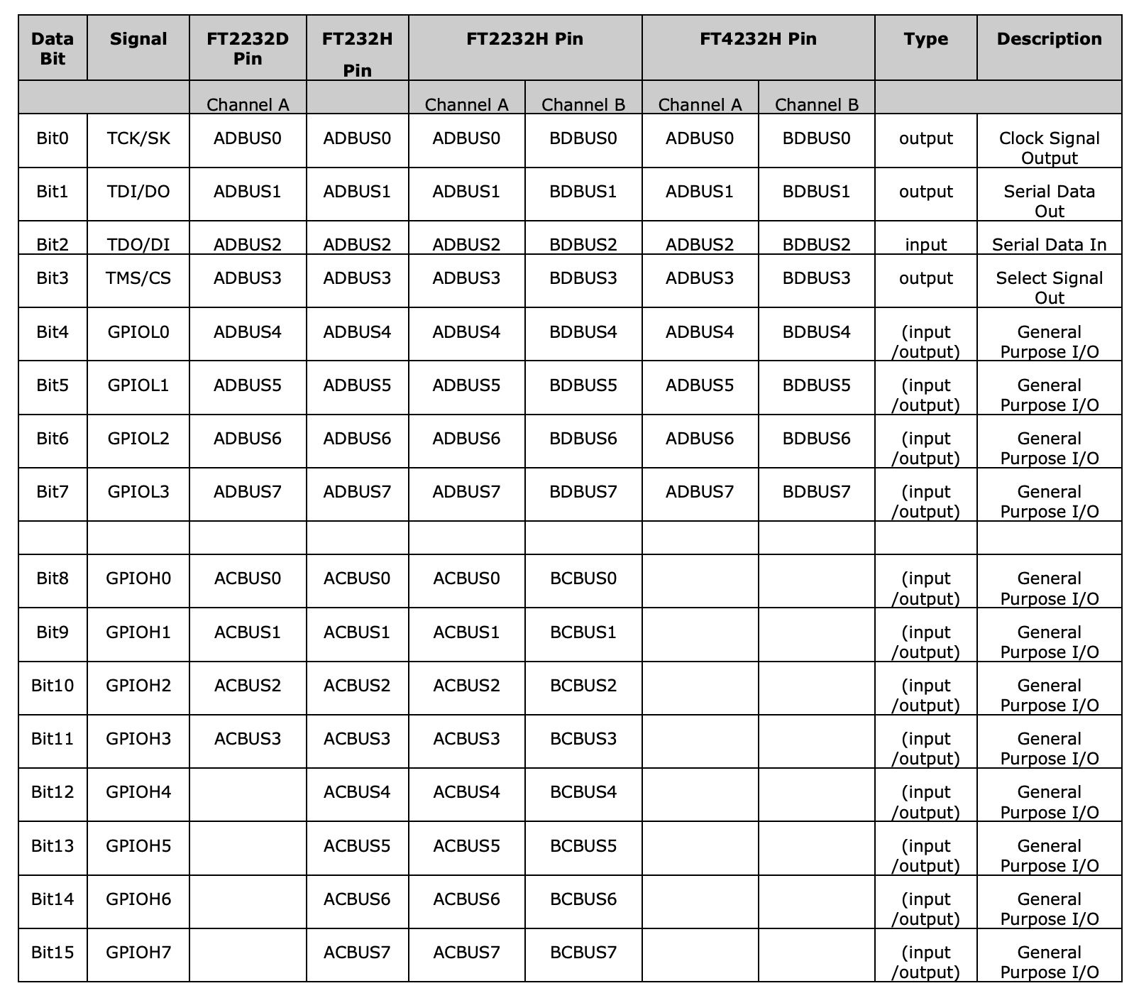
We only care about the first 4 bits which are the ones used for JTAG a lot of the others are just general purpose IO that you can connect to anything and a lot of them are usually not used.
MPSSE is a mode we can put the FTDI chip into to accept special commands for sending serial data out over these lines replicating different serial protocols.
So for standard FTDI commands we only really want to do 3 things:
- Set the communication baud rate
- Set the latency timer
- Turn on MPSSE mode
Once we do this all the other commands will be special MPSSE commands. FTDI commands are sent as normal control transfers like we sent above to the device to retrieve descriptors whereas the MPSSE commands will be data sent over the JTAG endpoint and handled by the FTDI IC.
To get started let's add a function to our page to send these FTDI packets.
async function sendUSBCommand(command) {
    if (!device) { return; }
    await device.open();
    await device.controlTransferOut({
        requestType: command.requestType || 'vendor',
        recipient: 'device',
        request: command.request,
        value: command.value || 0x00,
        index: command.index || 0x00
    });
    await device.close();
}
This is very similar to our function to get descriptors, except we are accepting a parameter which can override the different fields inside of the control transfer directly. Also we are using control transfer out since we don't need to read anything here.
With this function we can create an initMPSSE function to initialize the ftdi device.
 async function initMPSSE() {
    // Reset ftdi port
    await sendUSBCommand({ request: 0x00, value: 0x0000, index: 0x00 });
    // Set baud rate 115200
    await sendUSBCommand({ request: 0x03, value: 0x001a, index: 0x00 });
    // Set latency timer to 8ms
    await sendUSBCommand({ request: 0x09, value: 0x0008, index: 0x00 });
    // Set MPSSE mode
    await sendUSBCommand({ request: 0x0b, value: 0x0200, index: 0x00 });
    // Flush RX buffer
    await sendUSBCommand({ request: 0x00, value: 0x0001, index: 0x00 });
    // Flush TX buffer
    await sendUSBCommand({ request: 0x00, value: 0x0002, index: 0x00 });
}
Looking again at the previous function, these are all control transfers, with requestType of vendor meaning a vendor specific command not part of the base USB spec, in our case these are FTDI commands.
I couldn't find a good source of documentation for these commands, so a bit of exploration is required, I found libftdi to be a good source of information among other open source projects like openFPGALoader which we have been using for programming the Tang Nano.
Let's go through the commands quickly, the first command we are sending is the reset command (request: 0x00) it has 3 sub-options, when you send a value of 0 it resets the port, if you send a value of 1 it will flush the rx buffer and a value of 2 will flush the tx buffer. We use all three variants here.
The next command we are using is the command to set the baud rate (request: 0x03) here you need to pre-calculate the value you want to send based on a formula, I found this document with a list of common values, here we are sending 00 1a which represents 26 in decimal. The way you basically get this value from my understanding is you take 3000000 and divide by the desired baud rate to get the divisor, and then you send this divisor to the FTDI which it will use to get to the correct baud rate.
We are sending 26 so 3000000/26 = 115,384.62 which is the closest to 115200 we can get with a whole number.
Next we set the latency timer (request 0x09), which sets the number of milliseconds to wait before sending the device buffer over USB without waiting for it to fill up. Here we are setting it to 8 or 8 ms.
The last command we didn't cover is the command to change the mode (request 0x0b) where we can send it the value 0x0200 to change into MPSSE mode. whats important here is the upper byte which we are setting to 0x02 which is what changes the device into MPSSE mode. The official docs say to change the mode first to 0x0000 or bitbang mode and then to MPSSE mode, I found at least for the clone it wasn't necessary, but I thought I would mention it.
With that we are now ready to start implementing JTAG.
The JTAG State Machine
JTAG is an interesting protocol, because unlike most protocols, where you are talking to another processor by sending it commands and getting back responses. With JTAG you are directly controlling a state machine called the TAP (test access port) state machine, moving from state to state to accomplish what you are trying to do.
Kind of like driving a car you don't just tell it where to go, you control the gas pedal, breaks and steering wheel to cause the car to go where you want it to go.
The standard JTAG (TAP) state machine looks as follows:

Basically you have two main "registers", the data register and the instruction register (DR and IR respectively) and you navigate around the state machine to modify either of these.
The way you navigate this state machine is by using the TMS pin and the numbers next to each arrow is the state this pin should be in when clocking TCK in-order to transition from one state to the other. For example if we were on "TEST LOGIC RESET" and wanted to get to "SHIFT DR" we would need 4 clock cycles of TCK and we would set TMS to 0 -> 1 -> 0 -> 0.
Once inside a state we can shift data in and out using the TDI and TDO pins (this will mostly happen in the SHIFT stages like SHIFT DR and SHIFT IR).
That's pretty much JTAG, being a generic protocol used for many different things, JTAG only provides the structure we need to take a look at the Gowin documentation to see how we need to "drive" the state machine in-order to interact with the FPGA.
This article is already pretty long, so we won't be able to cover implementing the whole JTAG process for programming the FPGA. Instead we will be doing the first step which is reading the devices ID code.
Each Gowin device family has a different code and the generated bitstream includes the code for the family the bitstream was generated for. So the first step to programming would be to read this code and compare it to the bitstreams code to make sure you are uploading the correct format.
If you ever received an ID code mismatch error when trying to program your FPGA this is the test which failed.
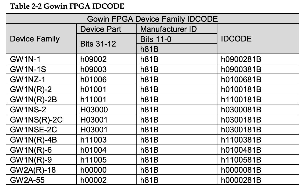
We are using the GW1NR-9C which is not included in the table above but the id code should be 0x1100481b.
Reading the ID Code
In-order to read the ID code of the device we need to do the following:

According to the Gowin document linked above we need to move the state machine to SHIFT IR, then enter the command into the instruction register by shifting it in, the code is 0x11, when we are on the last bit of the instruction we need to move to EXIT1 IR which we can do by setting TMS to 1.
From there we need to go to the UPDATE IR state then back to the IDLE state to wait for the reply. From their we can go to SHIFT DR to shift in the 32-bits of the ID code again moving to the EXIT1 state at the last bit.
With the ID code read we go to the UPDATE DR state and the back to idle. This might seem like a lot of steps for getting the ID code, but again we are not requesting the code directly from the FPGA, we are driving the JTAG state machine in order for it to get the ID code from the FPGA.
In-order to implement this we need a way to control TMS to transition states, a way to shift data into the device like the command 0x11 to read the idcode and we need a way to shift data out from the FPGA for getting the actual ID out.
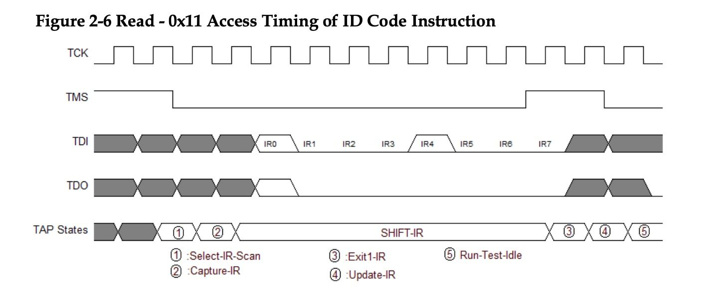
Conveniently we even have a complete timing diagram in the Gowin JTAG docs here

Above you can see a picture of the first half of the flow, let's break it down by signal. On top we have a clock signal TCK this will be handled automatically by MPSSE, in this diagram you can see we have an active low clock signal and we update the other lines on the falling edge and read data on the rising edge.
TMS is again used to traverse the TAP state machine, this diagram assumes we are in the run-test-idle stage, and you can see we have 2 clock pulses with TMS high moving to SELECT IR SCAN, from there another two pulses with a low TMS value moves us into SHIFT IR.
Inside SHIFT IR we start passing the 8 bits of our command code (0x11) least significant bit first. On the last bit we need to both shift data in over TDI and set TMS high at the same time to transition to EXIT1-IR.
TDI and TDO are our data lines for writing and reading data respectively. The rest of the process for reading the ID code is exactly the same, just we go to SHIFT DR instead and read 32-bits instead of writing 8, but it has the same process of modifying TMS to get to the correct state and then shifting bits until the last one and then on the last bit updating TMS to move on to the EXIT state.
Implementing JTAG over MPSSE
With the theory out of the way, we know what we want to do, what is left is how to do it. MPSSE is a protocol that provides a lot of flexibility for recreating pretty much any serial protocol that revolves around clocking data in or out via 2-3 pins.
To accomplish this level of genericism it has a very granular command structure for controlling these pins:
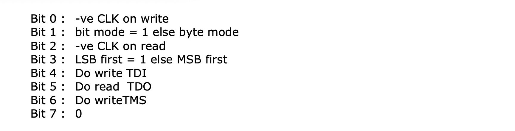
So whenever the 8th bit (bit-7) is 0 it means we are dealing with a data transfer command, and then each of the other bits controls a different aspect of the transfer.
The first bit controls whether we write on the rising edge or falling edge, and the third bit is the same for when to latch data in whether it should be on the rising or falling edge.
The second bit is used to set whether we are sending a number of bytes or bits in the current command. In byte mode we can write / read multiple bytes with a single command and it will clock them in/out serially allowing for large transfers, and in bit mode we can send as little as a single bit allowing for fine-grained control.
The fourth bit will determine whether we are sending data least significant bit first or most significant bit first.
Next we have 3 flags. Setting the first will cause data to be clocked out over TDI to the FPGA, setting the next flag will cause data to be clocked in over TDO and setting the final flag will cause data to be clocked out over TMS.
Now there are some rules here, like you need at least one of the flags to be on, and you can't write data to both TDI and TMS at the same time (although there is a way as we will see soon). But you can read data over TDO no matter what the state of the other flags are, so you can read data and control TMS, or read data while shifting data out to TDI.
As you can see the protocol is very flexible and allows for fine-grained control over each of the 3 control pins. The clock pin will be automatically pulsed per operation and handled behind the scenes, so for example if we send an MPSSE command to shift out 3 bits, it will automatically take the data of those 3 bits and shift them out 1 at a time for each performing a full clock cycle on TCK.
Here is a chart with some of the LSB commands for reading and writing data over TDI / TDO:
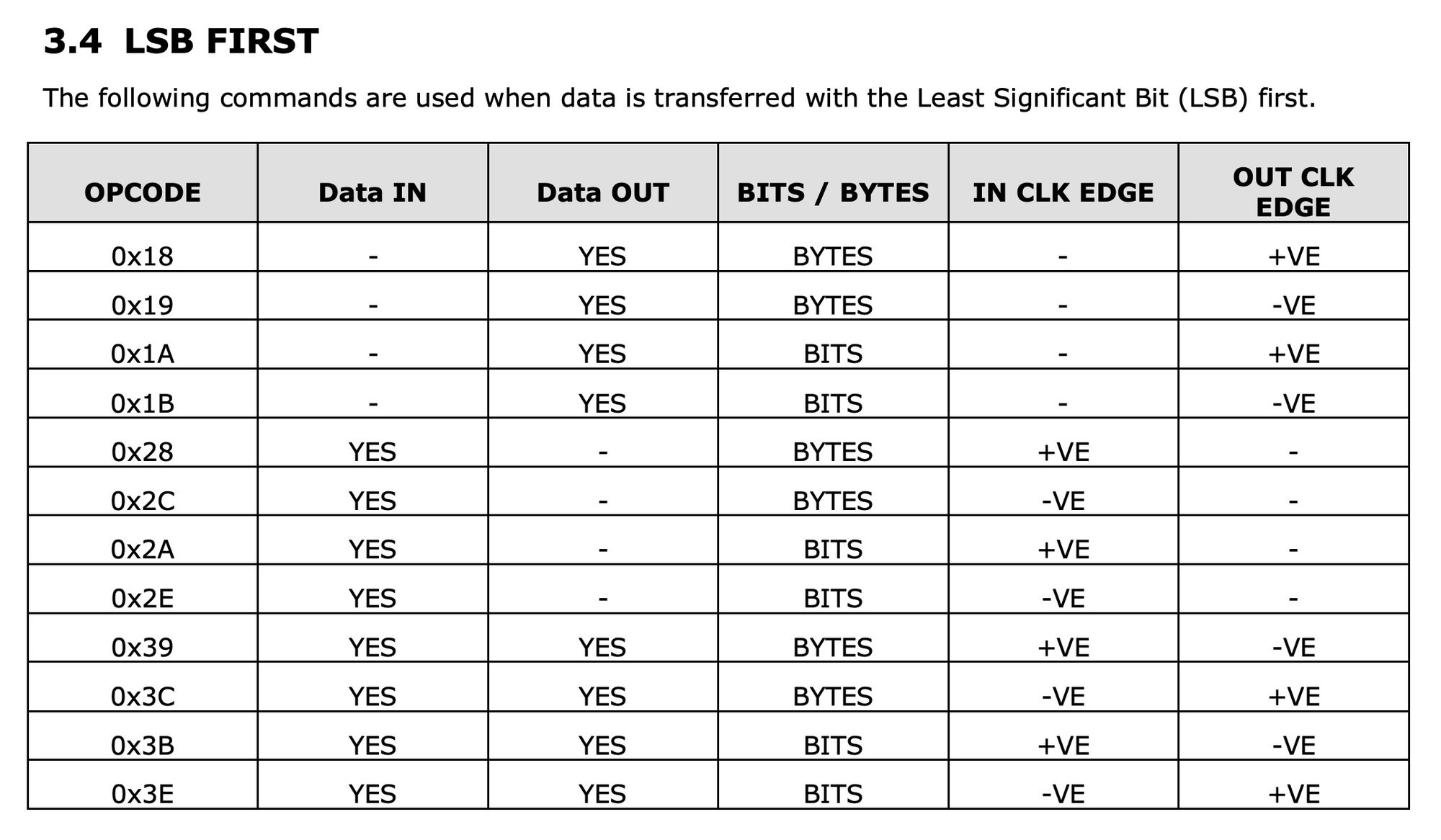
If we take a look at 0x39 for example, this in binary would be 00111001 and looking back at our chart:

bit 0 is high and bit 2 is low meaning the command writes on the falling edge and reads on the rising edge like we see in the table. We are also in byte mode as bit 1 is a zero. The byte will be read/written least significant bit first since bit 3 is high. Finally this is both a write over TDI and a read over TDO but not a write over TMS because of how the flags in bits 4-6 are set.
Applying MPSSE To FPGAs
In our example we saw we need to re-create the following signals:
The first thing we need to to is move the TAP state machine to Shift IR which requires us sending 4 clock cycles with the values on TMS of 1 1 0 0. So to get the correct MPSSE command let's break it down step by step. We need to send 4 bits over TMS, so we know bit-1 will be a 1 to represent bit mode instead of byte mode and we know we will be writing on TMS so bit-6 will also be high.
01xxxx1xFrom the image we can also see that data is written on the falling edge of the clock and is read on the rising edge so we can fill in bits 0 and 2.
01xxx011Regarding using the least significant bit or most-significant bit it doesn't really matter because it would only affect how you would have to send the bits, but let's use LSB since you can see in the next step when sending the instruction it expects LSB. Finally we know we can't write to TDI and TMS at the same time so bit-4 will be low, and we don't need to read anything so we can set bit-5 also low.
Altogether this would give us:
01001011Or 0x4B in hex, taking a look at the docs we can get more info on this command:
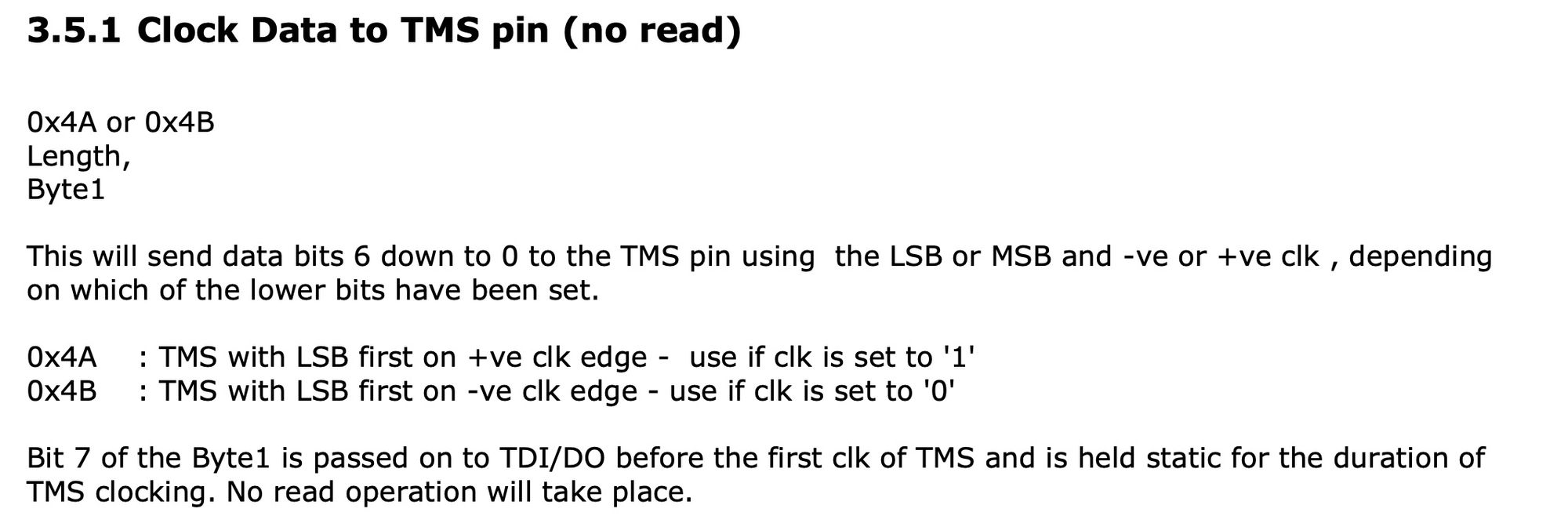
To use this command you send 3 bytes, the first being 0x4B, followed by a byte describing the number of bits you want to send minus one, so a value of 0 means send 1 bit, and finally you have the data byte called byte1 which contains the data we want to send. You can see that the highest bit of this byte is actually used to set the value of TDI for the duration of all TMS clock cycles.
This is exactly what we need when we finish shifting in data, we need to send the last bit and jump to the next TAP state, so using this functionality we can both set TDI and TMS (at least for 1 bit). But we are getting a bit ahead of ourselves, to wrap it up, we want to send 4 bits so we would set length to 3 and we want TMS to be 1 -> 1 -> 0 -> 0 and we are sending the data LSB (and let's say we set TDI to 0) then we would send 0b00000011 (or also 0x03) so that the least significant bit will be the first transition.
Altogether to send the first command we would send [0x4B, 0x03, 0x03]
Next we need to send 7 bits over TDI with the instruction to get the ID code of the FPGA (0x11) so following the same strategy for finding the command and parameters we would need to send: [0x1B, 0x06, 0x11].
This will only send the lower seven bits, meaning we still need to send the last zero and shift into the EXIT IR state, which we can do with the previous command: [0x4B, 0x00, 0x01]. This would send the last bit of the command (which is a zero) and set TMS high, causing us to go to EXIT-IR.
Follow this up with another 1 -> 0 transition over TMS and we get back to RUN TEST IDLE: [0x4B, 0x01, 0x01]. We could have combined the last two commands and just sent 3-bits over TMS at once, but I separated to stress the maneuver setting both TDI and TMS at the same time.
I won't go through the rest of the process step by step but you can follow this process to see how I got to the final bytes that need to be sent:
0x4B, 0x03, 0x03 // move to shift IR
0x1B, 0x06, 0x11 // shift in instruction 0x11 (lower 7 bits)
0x4B, 0x00, 0x01 // shift in highest bit moving to exit1 ir
0x4B, 0x01, 0x01 // move to run test idle
0x4B, 0x04, 0x00 // poll for 5 clock cycles in run test idle
0x4B, 0x02, 0x01 // move to shift dr
0x39, 0x02, 0x00, 0x00, 0x00, 0x00 // read 3 bytes of our ID code via TDO
0x3B, 0x06, 0xFF // read another 7 bits of our ID code
0x6B, 0x00, 0x01 // read the last bit and move to exit1 dr
0x4B, 0x01, 0x01 // move back to run test idle
One small comment here would be that for reading the bytes from DR instead of using 0x39 and 0x3B which both read from TDO and write to TDI, I would have used 0x28 and 0x2A without a payload which only read from TDO since we don't really want to write anything. The reason I used the other commands is because it doesn't look like 0x28 or 0x2A were implemented on the BL702 FTDI clone which you can see here so we use the next best thing which just requires sending a few extra bytes.
Some Initialization
With our payload done, we just have a few more MPSSE commands to learn about, the first two are used for initialization:
- 0x86 - this sets the clock divisor, we can just set this to 0 to go full speed
- 0x80 and 0x82 - these setup the 16 pins from the FTDI device in terms of initial value and direction (input or output).
Besides for these commands we also have the 0x87 command which flushes the buffers, causing any pending data to be sent / received immediately, this is useful when you have commands that require waiting after them, for example between setting the IR register and reading from the DR register. In situations like these you need to flush the buffer to have an accurate timing.
The last thing I want to talk about before we implement this is resetting the TAP state machine.

The state machine is configured such that no matter where you are if you send 5 '1's in a row over TMS you will get back to TEST LOGIC RESET. This is important for regaining your bearings and for initializing the state machine, as we can send 5 ones followed by a zero to initialize our place on RUN TEST IDLE which is the assumption we made above. This can be achieved with [0x4B, 0x05, 0x1F]
Implementing Get ID Code
Back in our JavaScript, we had just finished the code to initialize the FTDI into MPSSE mode. We now need to create a function to allow us to send MPSSE commands.
MPSSE commands are sent over a regular endpoint as opposed to the FTDI commands we sent over the special control endpoint.
async function sendMPSSECommand(data) {
    if (!device) { return; }
    await device.open();
    const id = device.configuration.interfaces[0].interfaceNumber;
    await device.claimInterface(id);
    const writeRes = await device.transferOut(2, new Uint8Array(data));
    const readRes = await device.transferIn(1, 64);
    await device.close();
    if (!readRes.data || readRes.data.buffer) { return []; }
    return Array.from(new Uint8Array(readRes.data?.buffer));
}
This function will accept an array of bytes to send, it will send that data over endpoint 2. As we saw from debugging WebUSB the first interface is the JTAG interface and it has two endpoints numbered 1 & 2 and 2 is the output endpoint and 1 is an input endpoint.
Before using an endpoint other then the control endpoint you need to claim it's interface which we do with the claimInterface function.
After each write we follow up with a read just in case the command had a response, we read up to 64 bytes of data, although the responses are much lower then this.
The last line of the function just checks if data was read, and if so it will return it in array form so it is easier to work with, otherwise if no data is read an empty array is returned.
With this function we can move onto the MPSSE initialization:
async function setupMPSSE() {
    await sendMPSSECommand([
        0x86, 0x00, 0x00, // Disable clock divisor
    ]);
    await sendMPSSECommand([
        0x80, 0x08, 0x0b, // Setup lower ftdi bits
        0x82, 0x08, 0x0b, // Setup upper ftdi bits
        0x87              // Send immediate
    ]);
    await sendMPSSECommand([
        0x4B, 0x05, 0x1F, // Reset TAP state machine
    ]);
}
The last thing to do is to send our payload:
async function getIDCode() {
    await sendMPSSECommand([
        0x4B, 0x03, 0x03,  // move to shift IR
        0x87               // send immediate
    ]);
    await sendMPSSECommand([
        0x1B, 0x06, 0x11,  // shift in instruction 0x11 (lower 7 bits)
        0x4B, 0x00, 0x01,  // shift in highest bit moving to exit1 ir
        0x87               // send immediate
    ]);
    await sendMPSSECommand([
        0x4B, 0x01, 0x01,  // move to run test idle
        0x87               // send immediate
    ]);
    await sendMPSSECommand([
        0x4B, 0x04, 0x00,  // poll for 5 clock cycles in run test idle
        0x87               // send immediate
    ]);
    await sendMPSSECommand([
        0x4B, 0x02, 0x01, // move to shift dr
        0x87              // send immediate
    ]);
    await sendMPSSECommand([
        0x39, 0x02, 0x00, 0x00, 0x00, 0x00, // read 3 bytes of our ID code via TDO
        0x87              // send immediate
    ]);
    // responses are delayed by 1 transmission
    const first3Bytes = await sendMPSSECommand([
        0x3B, 0x06, 0xFF, // read another 7 bits of our ID code
        0x6B, 0x00, 0x01, // read the last bit and move to exit1 dr
        0x87              // send immediate
    ]);
    const lastByteRes = await sendMPSSECommand([
        0x4B, 0x01, 0x01, // move to run test idle
        0x87              // send immediate
    ]);
    const bytes = first3Bytes.slice(2);
    const upperBit = lastByteRes[lastByteRes.length - 1];
    const lowerBits = lastByteRes[lastByteRes.length - 2];
    const lastByte = (upperBit & (1 << 7)) | (lowerBits >> 1);
    return [...bytes, lastByte];
}
Mostly just sending the payload as we saw it above in smaller packets (the FTDI has a max buffer size of 64 bytes but other then that the division is pretty flexible).
I sprinkled in 0x87 send immediates here and there just to make sure the FTDI flushes the buffers out to the FPGA, so we know the buffer is empty and that the command has gone through.
One thing to notice is the the responses are transferred back to us delayed by one transmission. When we send the command over the USB endpoint, it is getting to the FTDI device, but at that time the action has not yet happened so we don't get a response. By the time we get to the next transmission the FTDI has already filled it's output buffer with the results of the previous command and then we can read it over the input endpoint which is what is causing the delay.
If instead of this setup you would be controlling the JTAG pins directly. You would get the bits as you toggled the TCK pin immediately.
The last thing to notice is that because of the EXIT1 DR maneuver we can only read 3 of the 4 bytes in byte-mode and the last byte we need to first read 7 bits and only then the last top bit while pulling TMS high. Because of this when we get the bytes back we will have two separate bytes corresponding to each of these reads that we need to combine to get the last byte. We shift the seven down since we are in LSB mode the bits are shifted from the top so the first bit read will be in the least significant bit place after shifting all the way in.
Because we only read seven and not 8 bits we need to shift it over 1 more place and then we combine it with the top bit from the next read.
Getting our Code
To test the code we did, we can simply update our event listener which is on the connect button to the following:
connectBtn.addEventListener('click', async () => {
    const newDevice = await navigator.usb.requestDevice({ filters: [] });
    setDevice(newDevice);
    await initMPSSE();
    await setupMPSSE();
    const code = await getIDCode();
    const codeInHex = code.reverse().map((byte) => {
        return byte.toString(16).padStart(2, '0');
    }).join('');
    console.log(codeInHex);
    deviceInfo.innerText = `ID Code: ${codeInHex}`;
});
Reloading the page and pressing on the connect button to connect our FPGA will trigger our code and print the ID code to the terminal and add it to the screen.
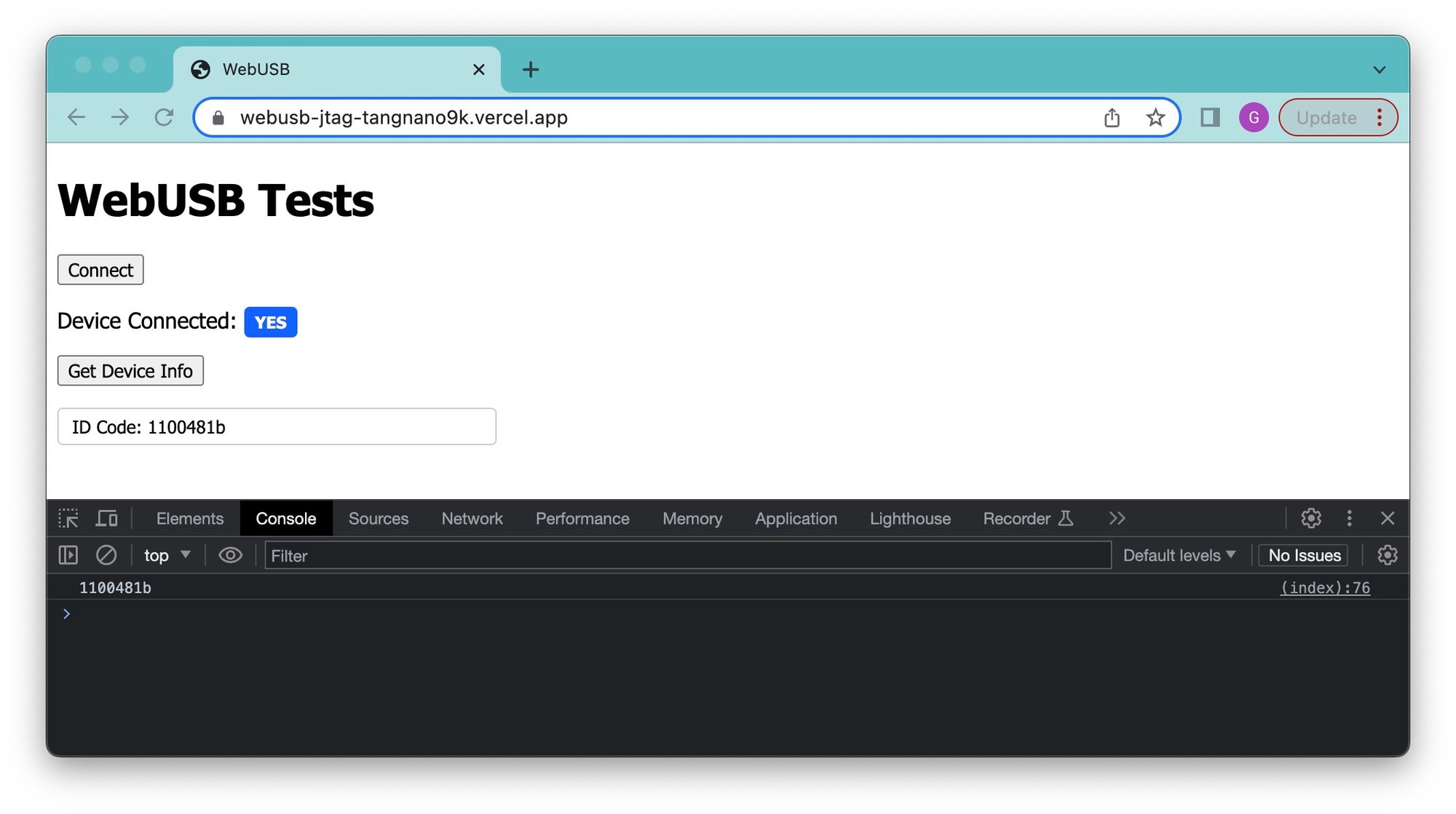
You can test this out with your tang nano using the hosted version here.
Programming the Bitstream
We won't get into it as this article is already longer then expected, but we set out to learn about the process of programming the bitstream so I at least want to go over the process.
We will take a look at programming the internal flash, the process for programming the internal SRAM is similar but a bit different.
For programming the internal flash we have the following diagram from the Gowin JTAG doc.
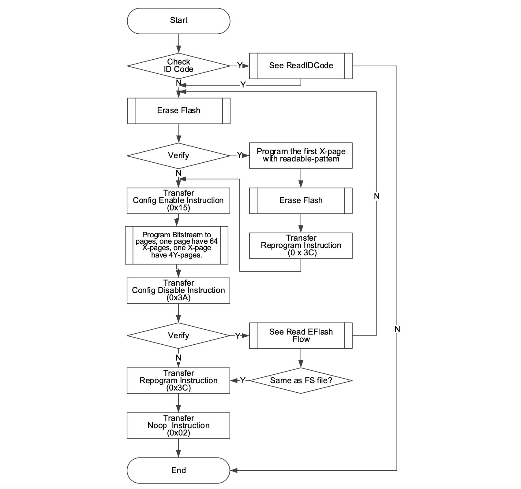
You start by reading the ID code of the device, like we just did, and then compare it to the ID code in the bitstream file. The bitstream itself starts with some headers, one of which indicates which device the bitstream was generated for. This check is to make sure you don't accidentally flash a bitstream for the wrong FPGA.
The next step if this passes is to erase the contents of the internal flash, this has its own sub-flow. Once the data is erased, there is a verification stage where you can verify that the flash has been erased.
The internal flash is split into what they call X-pages which are 256 byte blocks, each of which are split into 64 4-byte chunks called Y-pages. The first Y page of the first X page is used to enable / disable reading the flash, so in-order to read the flash you need to place here a special sequence of bytes called the readable pattern, it is something like (depending on FPGA):
0xF7,0xF7,0x3F,0x4FThat is why for the verification it says to write this pattern in so that the flash can be verified. If the flash is in its factory state we also send the Transfer Reprogram Instruction which copies whatever is in flash into the SRAM. Essentially since we just wiped the flash it will clear the SRAM as-well.
Back to the main flow, we need to send the config enable instruction which will allow us to use program an X-page (this is done at the verification stage above also). You then move onto programming each X-Page in the bitstream passing all bytes from the bitstream file into the FPGA.
Once done you can disable configuration and then re-read the flash back to verify that it is what you sent. Finally we re-run the "Transfer Reprogram" instruction to load up the flash into SRAM starting your bitstream. The docs also claim you should end with a No-Op instruction at the end to complete the programming procedure, so I will take their word for it.
Conclusion
In this article we went through the many different protocols which work together to allow us to simply program our FPGAs from a computer, hopefully providing new appreciation for this daily task we might take for granted some times.
Ways to take this project further, I would suggest starting with some "read-only" commands like reading the SRAM or even writing to the external flash before reprogramming the FPGA to gain more confidence first, but I have used this method for things like erasing the bitstream from the Tang Nano flash without any issues.
Thank you for making it to here I hope you enjoyed reading. This article is a bit different then our regular content, so let me know if you would like to see more articles like this.
As always all the code can be found on Github, the repo for this project can be found here. The hosted web version of this page can be found here.
If you have any questions or comments feel free to leave them down below in the comments section or DM me on twitter (X?) here.
